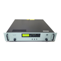
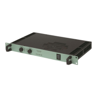
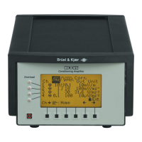
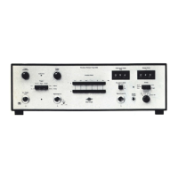
Measuring Ampifier Type 2525
User Manual Vol.2
5–3
BE1394– 11
Chapter 5 – General Control Messages
Status and Configuration Check
5.3 Status and Configuration Check
5.3.1 Introduction
The amplifier has a status reporting system consisting of two event registers and a
status byte. Events are recorded in the event registers for later read-out via the
interface. Each event register has an associated event enable register with a mask
bit for each bit in the event register.
The event enable register controls the transfer of the current status of each event
register to a specific bit position in the Status Byte. The Status Byte has a bit
position for each event register type in the system.
By enabling one or more bits in the event enable register, the interface programmer
can specify which of the events recorded in the event register is to set the corre-
sponding bit in the Status Byte. In this way the Status Byte can be used to observe
specific events taking place during amplifier operation.
For any enabled bit in an event enable register, the corresponding event bit in the
corresponding event register are passed through a logical AND to set the appropri-
ate bit in the Status Byte. A logical OR (see Fig.5.2) is used thereafter so that
regardless of the number of Event/Event Enable Register bit-sets that are enabled,
only one bit is set in the Status Byte.
The content of the event registers can only be cleared using the interface command
Reset or Reset_Single (see section 5.4.1). Register read-outs are non-destructive.
5.3.2 Measurement Status
Measurement_Status?
The content of the Measurement_Status event register is read using the query
message:
Channel_1:Measurement_Status?
The response is an integer with a value that can be decoded using Table 5.1.
Note: Since the information contained in the event register is bit-encoded, the re-
sponse value must be decoded to determine which events were recorded in the
event enable register.
Example:
A response value of 13 means that bit 1, bit 3 and bit 4 were set, corresponding to
Common_Mode_Overload, ALArm and Deltatron_Error.
 Loading...
