Measuring Ampifier Type 2525
User Manual Vol.2
Brüel & Kjær
3–2
Chapter 3 – The Serial Interface
Hardware/Functional Specifications
3.1 Hardware/Functional Specifications
This section describes the physical level of the serial interface. The serial interface
of the 2525 conforms to EIA/TIA 574, which is equivalent to the RS–232, however
with a 9-pin connector.
The interface of the 2525 is coupled as “Data Terminal Equipment” (DTE), and
operates in full duplex mode, which means that the interface is capable of operating
in both directions simultaneously.
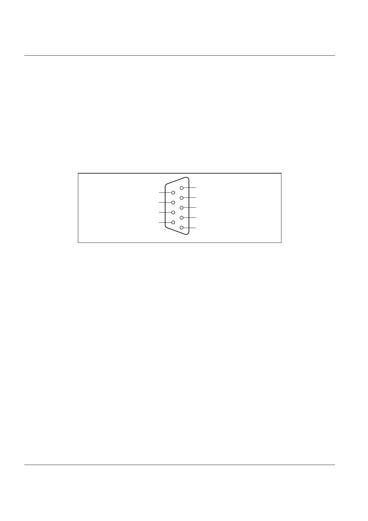
3.1.1 Serial Interface Connector
The interface connector is a 9-pin D-range male connector. It is located on the rear
panel of the 2525; see Volume 1 of this User Manual (section 3.2) for details. Fig. 3.1
shows the numbering of the pins on the connector. Pin definitions are given in
Table 3.1.
3.1.2 Data Lines
Pins 2 and 3, Received Data and Transmit Data, are data lines. For data lines, EIA/
TIA–574 specifies that:
● A voltage below –3 V signifies a binary 1
● A voltage above +3 V signifies a binary 0
● When a data line is passive, it is held in the binary 1 condition.
Data transmission is asynchronous as illustrated in Fig.3.2.
3.1.3 Control Lines
Pins 1, 4, 6, 7, 8 and 9 are the connections for the control lines. For control lines,
the EIA/TIA–574 standard specifies that:
● A voltage above +3 V signifies the on state
Fig.3.1 The 9-pin serial interface connector for the 2525
941654e
9
8
7
6
5
4
3
2
1
Data Set Ready (DSR)
Ring Indicator (RI)
Clear to Send (CTS)
Request to Send/
Ready for Receiving (RTS)
Received Data (RD)
Data Carrier Detect (DCD)
Signal Ground (Common)
Data Terminal Ready (DTR)
Transmitted Data (TD)

 Loading...


