Measuring Ampifier Type 2525
User Manual Vol.2
3–3
BE1394– 11
Chapter 3 – The Serial Interface
Hardware/Functional Specifications
● A voltage below –3 V signifies the off state.
The use of the control lines is described further in section 3.2.3.
3.1.4 Cables
A null-modem cable must be used to interface the 2525 to another DTE-coupled
device (computer). Interface cables can be ordered from Brüel&Kjær.
Pin
No.
Line Names Mnemonic Directions
1 Received Line Signal Detector
(Data Carrier Detect/Carrier detect)
RLSD
(DCD/CD)
To 2525
2 Received Data R×D (RD) To 2525
3 Transmitted Data T×D (TD) From 2525
4 DTE Ready (Data Terminal Ready) DTR From 2525
5 Signal Common (Ground) SG –
6 DCE Ready/ Data Set Ready DSR To 2525
7 Request to Send RTS From 2525
8 Clear to Send CTS To 2525
9 Ring Indicator Ri To 2525
Table 3.1 Pin definitions for the serial interface according to the
EIA/TIA–574–1990 Standard. Line names and mne-
monics in parentheses are the commonly used names
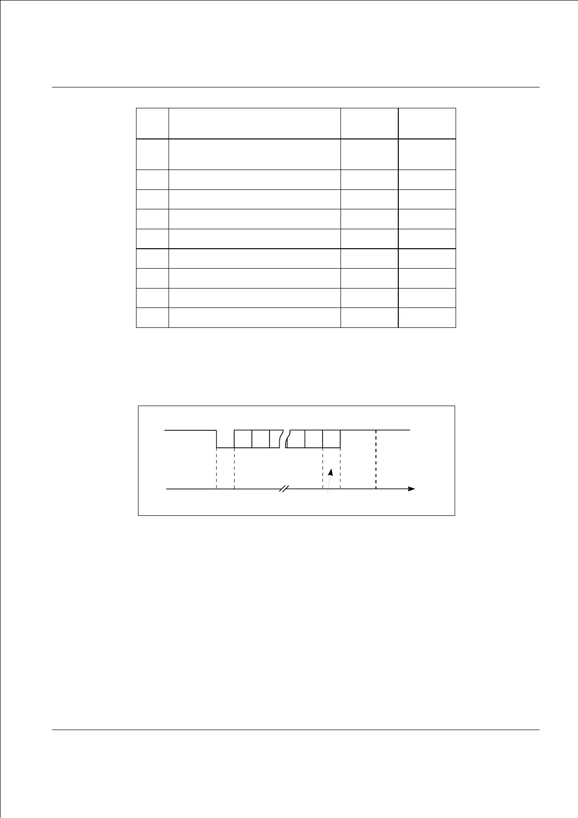
Fig.3.2 Asynchronous transmission of 1 byte of data
911511e
Binary
Data Line
Time
Line Passive
Stop
Bit(s)
Data Bits
Start
Bit
Line Passive
0
1
Parity Bit
(optional)

 Loading...


