3-36 2003 Buell P3: Engine
HOME
PUSH ROD COVER INSTALLATION
NOTE
Push rod cover must be installed prior to installing cylinder
head.
1. See Figure 3-64. Install push rod cover.
a. Install new o-rings (2) on top of each push rod cover
(3).
b. Install new push rod cover gasket (5) onto bottom of
each push rod cover.
c. Install push rod cover assembly and start the four
fasteners (4) securing bottom of cover to crankcase.
d. Tighten fasteners to 30-40 in lbs (3.4-4.5 Nm).
2. See Table 3-23. Identify push rod color coding, length
and respective push rod positions in engine. Place intake
and exhaust push rods onto seat at top of tappet.
CAUTION
After head has been installed do not turn engine over
until both push rods can be turned with fingers. Other-
wise, damage to push rods or rocker arms may result.
Figure 3-64. Push Rod Location
Table 3-23. Push Rod Selection
POSITION
COLOR
CODES
LENGTH PART NO.
Exhaust 1 Band-
Black
10.969 in.
(278.613 mm)
17985-00Y
Intake 1 Band-
Orange
10.915 in.
(277.241 mm)
17984-00Y
7677
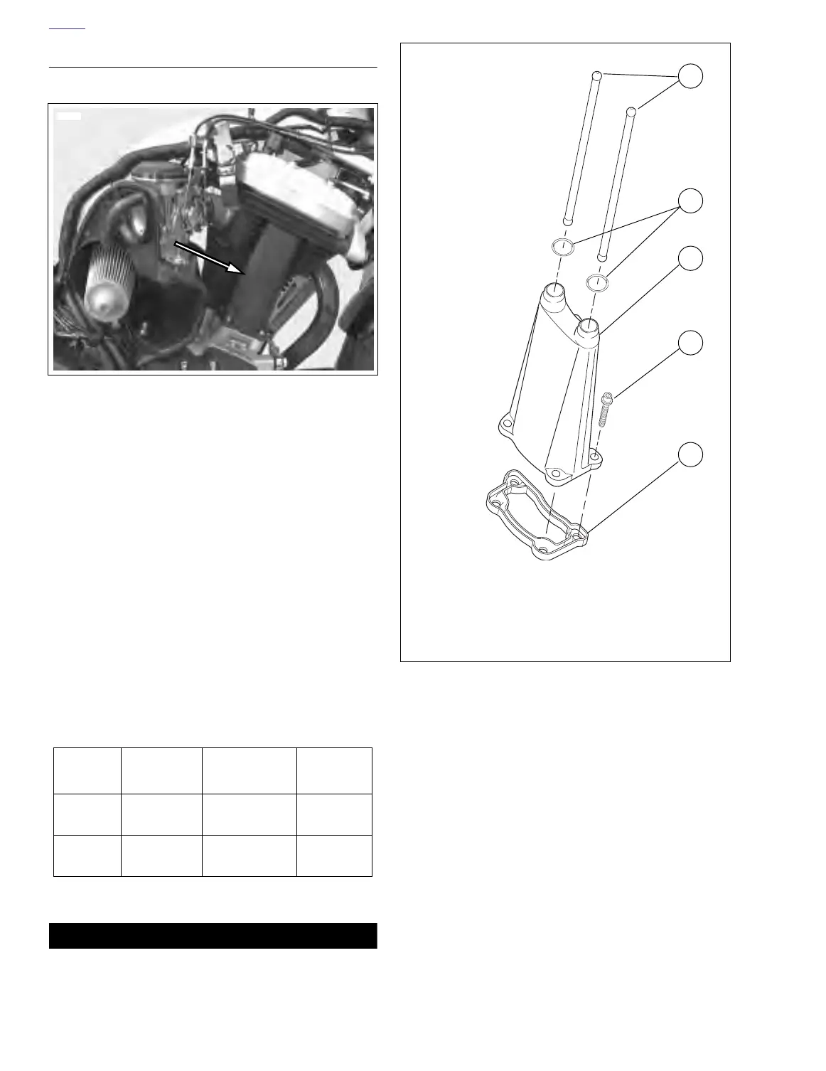
Figure 3-65. Push Rods and Push Rod Cover Assembly
b1092x3x
1
2
3
4
5
1. Push rod (2)
2. O-ring (2)
3. Push rod cover
4. Screws (4)
5. Push rod cover gasket