3-64 2003 Buell P3: Engine
HOME
REMOVAL/DISASSEMBLY
11WARNING1WARNING
Low pressure compressed air can blow debris into your
face and eyes. Always wear eye protection or a face
shield when using pressurized air. Failure to take ade-
quate safety precautions could result in death or serious
injury.
1. See Figure 3-103. Thoroughly clean area around gear-
case cover and tappets. Blow loose dirt from crankcase
with compressed air.
2. Remove any parts that will interfere with gearcase disas-
sembly.
3. See 3.5 CYLINDER HEAD. Remove push rods.
4. See 3.14 HYDRAULIC LIFTERS. Remove hydraulic lift-
ers.
5. Check for minimum cam gear end play. Record readings.
6. See 7.8 IGNITION MODULE AND CAM POSITION
SENSOR. Remove cam position sensor and rotor from
gearcase cover.
7. Place a pan under gearcase to collect oil. Remove cover
screws. Carefully remove gearcase cover. Discard old
gasket.
NOTE
If cover does not come loose on removal of screws, tap lightly
with a plastic hammer. Never pry cover off.
8. Remove cam gears.
NOTE
Nut is secured by LOCTITE 262 (red) on the nut threads.
9. Remove nut. Slide pinion gear and oil pump drive gear
off pinion shaft.
CLEANING AND INSPECTION
1. Thoroughly clean gearcase compartment, gearcase
cover and gears in solvent to remove oil and carbon
deposits.
11WARNING1WARNING
Low pressure compressed air can blow debris into your
face and eyes. Always wear eye protection or a face
shield when using pressurized air. Failure to take ade-
quate safety precautions could result in death or serious
injury.
2. Blow out all cover oil passages and bushings with com-
pressed air.
3. Clean old gasket material from gearcase and cover faces
with cleaning solvent.
Cam and Pinion Gear Identification,
Inspection, and Selection
See Figure 3-104. Cam lobes are stamped with a number (1
or 2) followed by a letter (“W”). The number (1 or 2) identifies
the cam location/function and the letter (“W”) indicates model
year application:
2W = Intake
1W = Exhaust
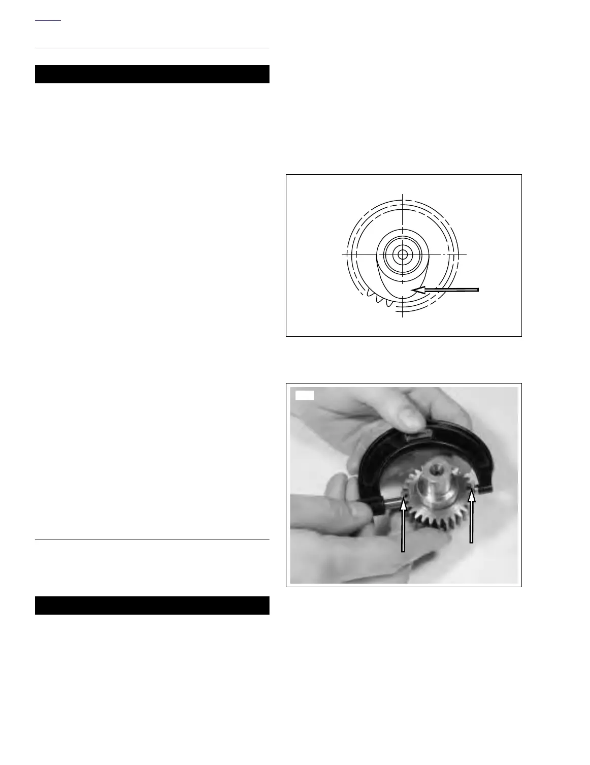
See Figure 3-105. Measure the gear diameter with a
micrometer over 0.108 in. (2.743 mm) diameter gauge pins
on opposite sides of the gear. The pins are of the proper size
to fit between the contacting surfaces of the gear teeth. Gear
diameter should be measured in at least two places 90°
apart. Use GAUGE PIN SET (Part No. HD-38361) when mea-
suring pinion and cam gear sizes.
Figure 3-104. Cam Identification/Stamped Numbers
Figure 3-105. Measuring Gear Size with Pin Set
(Part No. HD-38361)
2W
a0075x3x
7673