2003 Buell P3: Engine 3-71
HOME
ASSEMBLY/INSTALLATION
1. See Figure 3-115. Install oil pump drive gear (6) and pin-
ion gear (3) on pinion shaft (1).
a. Install shaft key (5) into pinion shaft slot.
b. Slide oil pump drive gear (6) over pinion shaft (1).
Drive gear must align with shaft key.
c. Align keyway (4) in ID of pinion gear with shaft key.
d. Slide pinion gear (3) over shaft key (5) and against
oil pump drive gear (6).
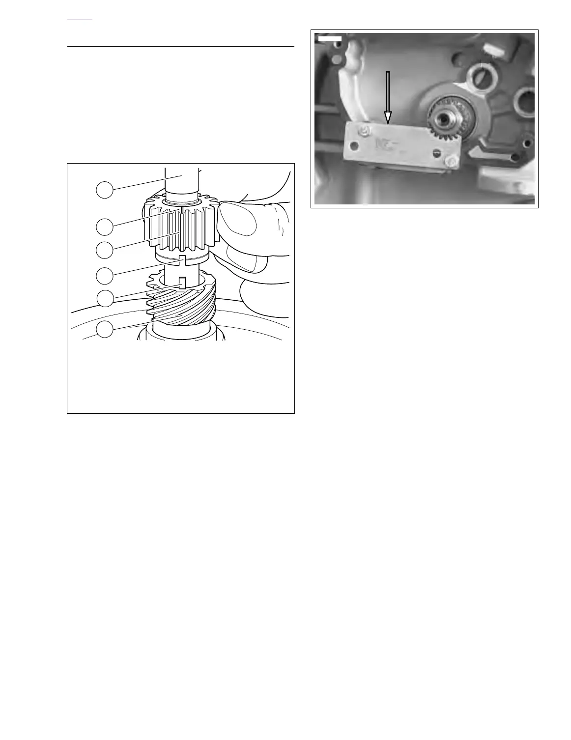
2. See Figure 3-116. Install nut.
a. Clean threads on pinion shaft and nut.
b. Install CRANKSHAFT LOCKING TOOL (Part No.
HD-43984) to gearcase with “Side B” facing out,
over pinion shaft, with two screws.
c. Apply several drops of LOCTITE 262 (red) to last
few threads of nut.
d. Install nut to pinion shaft. Tighten nut to 19-21 ft-lbs
(26-29 Nm) plus an additional 15 to 17 rotation.
3. See Figure 3-103. Liberally apply engine oil to bushings,
shafts, and gears. Install all cam gears into bushings of
right crankcase half, properly aligning timing marks of
cam gears and pinion gear.
NOTE
Because of the larger diameter additional gear (which
meshes with the pinion gear) on the outboard end of the cam,
the exhaust cam gear must be installed before the intake cam
gear is installed.
4. See Figure 3-103. Install a new seal and new dry gear
cover gasket on crankcase.
Figure 3-115. Aligning Pinion Gear
1. Pinion shaft
2. Timing mark on pinion gear
3. Pinion gear
4. Keyway
5. Shaft key
6. Oil pump drive gear
a0078x3x
1
2
4
5
6
a0078x3x
3
Figure 3-116. Crankshaft Locking Tool (HD-43984)
°
°
 Loading...


