2003 Buell P3: Electric Starter 5-19
HOME
ASSEMBLY
1. See Figure 5-26. Clean, inspect and lubricate drive
assembly components. Lubricate parts with high temper-
ature grease, such as LUBRIPLATE 110.
2. See Figure 5-26. When installing drive assembly compo-
nents, open end of idler bearing cage (19) faces toward
solenoid.
3. When installing drive housing (16) to solenoid housing
(24), use new o-ring (17). Be sure to install return spring
(23) and ball (22).
4. Lubricate armature bearings (10) with high temperature
grease, such as LUBRIPLATE 110. Install armature (11)
and field frame (7) to solenoid housing (24).
5. Install brushes and brush holder (4).
6. Install o-rings (5). Attach end cover (3) with end cover
screws and o-rings (2).
7. Install thru-bolts (1).
8. Attach field wire (9) to solenoid housing (24) with field
wire nut and washer (8) (metric). Replace rubber boot.
INSTALLATION
1. Install starter and starter gasket from the right side.
2. See Figure 5-27. Connect wiring to starter.
a. Connect solenoid wire (2).
b. Attach positive battery cable ring terminal (1) and
install nut with washer (1) (metric). Tighten to 80-
100 in-lbs (9-11 Nm).
c. Replace protective boot.
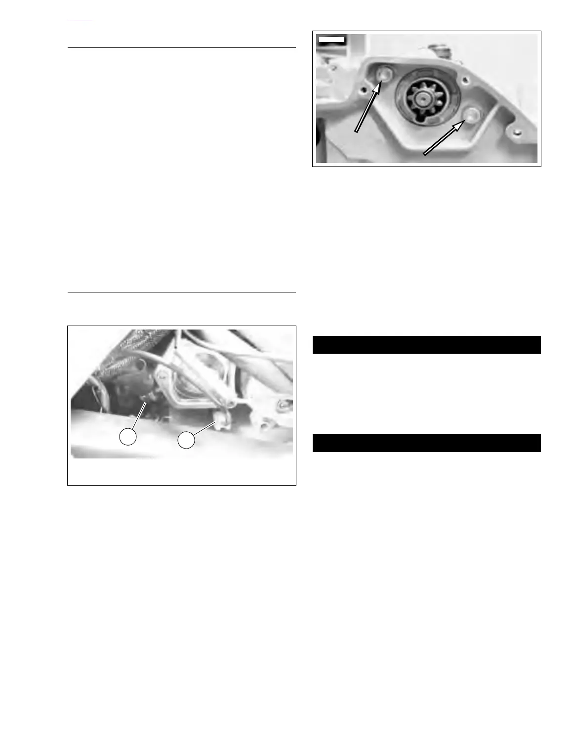
3. See Figure 5-28. Install both starter mounting bolts and
washers. Tighten to 13-20 ft-lbs (18-27 Nm).
4. Position oil hoses in clamp and install clamp to through
bolt with new locknut. Make sure hoses are not kinked or
restricted.
5. Install primary cover. See 6.2 PRIMARY CHAIN.
6. Fill transmission to proper level with fresh lubricant. See
1.10 TRANSMISSION/PRIMARY FLUID.
7. Install left side footrest support assembly. See 2.21
FOOTPEGS AND FOOTPEG SUPPORT BRACKETS.
8. Install air cleaner. See 4.3 AIR CLEANER.
Always connect positive battery cable first. If the positive
cable should contact ground with the negative cable
installed, the resulting sparks could cause a battery
explosion which could result in death or serious injury.
9. Connect battery cables, positive cable first. TIghten ter-
minal hardware to 60-96 in-lbs (7-11 Nm).
After installing seat, pull upward on front of seat to be
sure it is locked in position. If seat is loose, it could shift
during vehicle operation and startle the rider, causing
loss of control and personal injury.
10. Install seat. See 2.28 SEAT.
Figure 5-27. Starter Wires
7768
1. Positive battery ring terminal
2. connector [128]
2
1
Figure 5-28. Starter Mounting Bolts and Washers
(Primary Side)