6-6 2003 Buell P3: Drive/Transmission
HOME
Primary Cover
1. Remove foreign material from magnetic drain plug.
Install plug and tighten to 14-30 ft-lbs (19-40.7 Nm).
2. Wipe gasket surface clean. Install
new
gasket on pri-
mary cover.
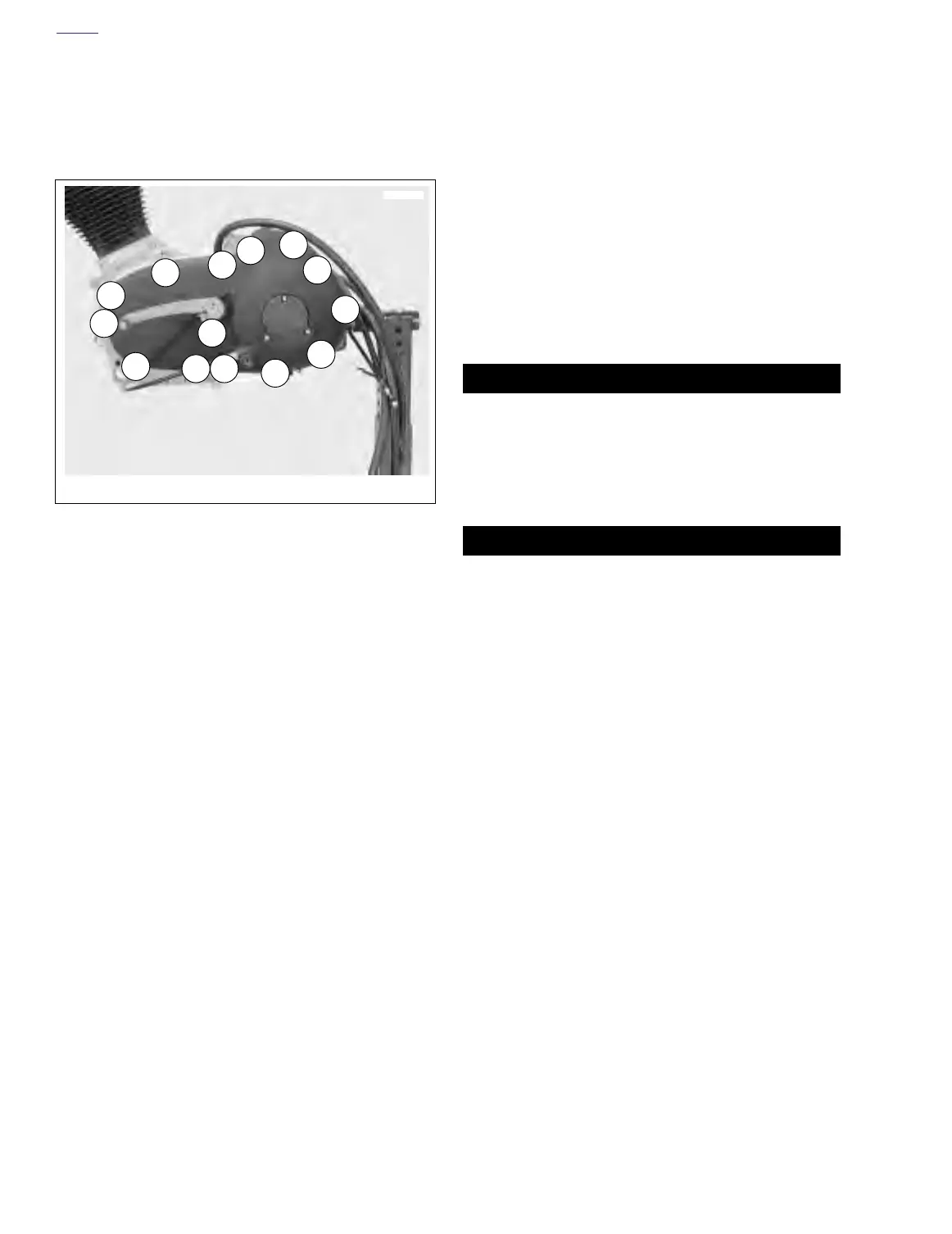
3. See Figure 6-7. Install primary cover and gasket onto left
crankcase half using mounting screws and tighten to
100-120
in-lbs
(11-14 Nm) in sequence shown.
4. See Figure 6-1. Install
new
shifter lever oil seal.
5. Fit coupling over cable end with rounded side inboard
and the ramp connector button outboard. With retaining
ring side of ramp assembly facing inward, place hook of
ramp around coupling button and rotate assembly coun-
terclockwise until tang on inner ramp fits in slot of pri-
mary cover.
6. Thread nut on adjustment screw until slot of screw is
accessible with a screwdriver. Fit nut hex into recess of
outer ramp and turn adjustment screw counterclockwise.
7. Adjust clutch. See ADJUSTMENT under 1.9 CLUTCH.
8. Adjust primary chain tension. See 6.2 PRIMARY CHAIN.
9. Fill transmission to proper level with fresh lubricant. See
TRANSMISSION under section 1.10 TRANSMISSION/
PRIMARY FLUID.
10. Install clutch inspection cover with
new
gasket and three
sems screws with washers. Tighten screws in a cross-
wise pattern to 84-108
in-lbs
(10-12 Nm).
11. See Figure 6-1. Install rubber washer and shifter lever
assembly and tighten pinch screw to 12-14 ft-lbs (16-19
Nm)
12. Install left footpeg support bracket. See 2.21 FOOT-
PEGS AND FOOTPEG SUPPORT BRACKETS.
11WARNING1WARNING
Always connect positive battery cable first. If the positive
cable should contact ground with the negative cable
installed, the resulting sparks may cause a battery explo-
sion resulting in personal injury and/or property damage.
13. Connect negative battery cable to battery terminal.
Tighten fastener to 60-96
in-lbs
(7-11 Nm).
11WARNING1WARNING
After installing seat, pull upward on front of seat to be
sure it is locked in position. If seat is loose, it could shift
during vehicle operation and startle the rider, causing
loss of control and personal injury.
14. Install seat. See 2.28 SEAT.
Figure 6-7. Primary Cover Tightening Sequence
1/4 x 20 x 2 Hex Socket Head (sems) --Qty 14
7667
6
1
7
8
9
11
10
2
13
3
14
4
5
12