6-8 2003 Buell P3: Drive/Transmission
HOME
ASSEMBLY
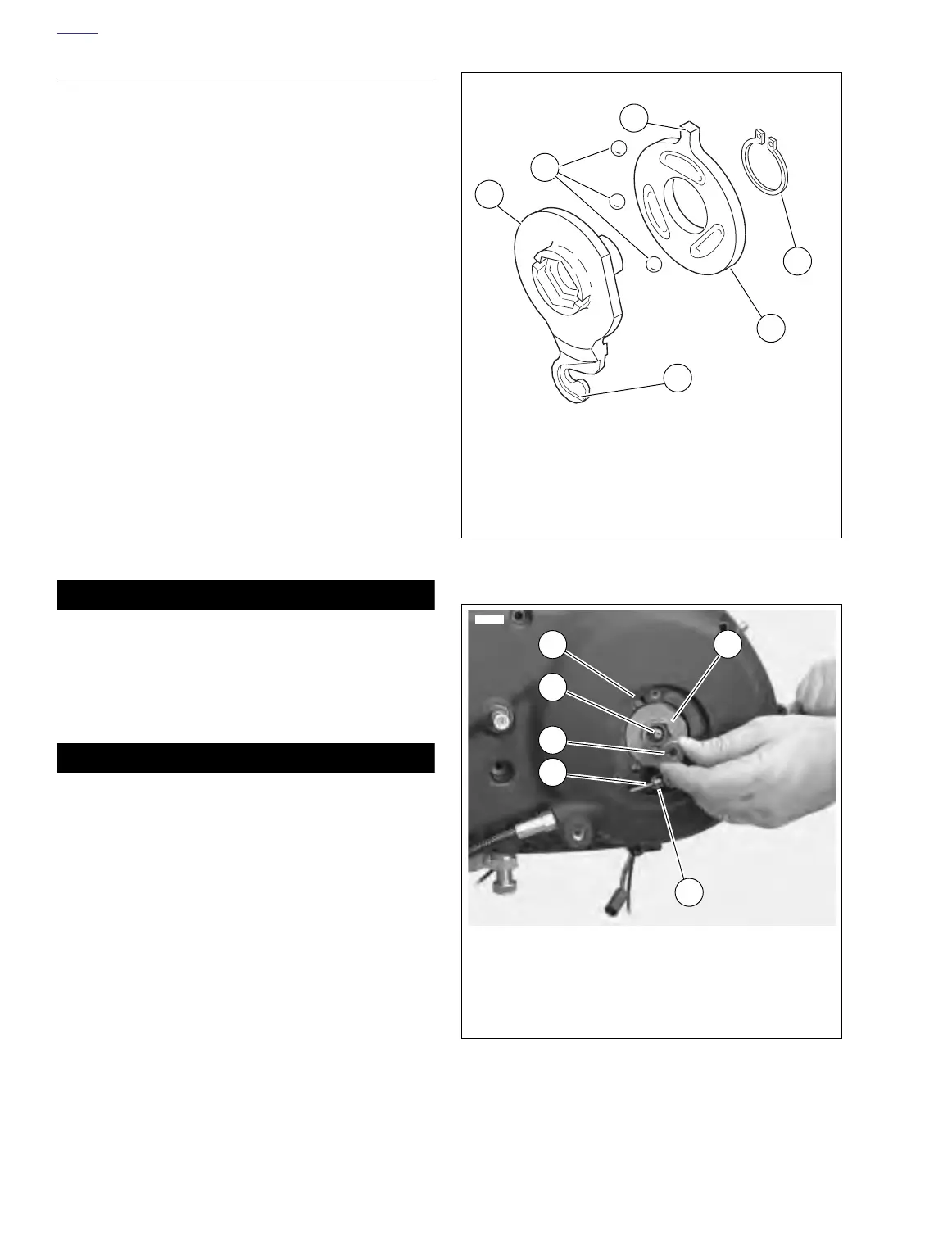
1. See Figure 6-9. Assemble inner and outer ramp.
a. Apply multi-purpose grease to balls and ramps.
b. Insert balls in sockets of outer ramp.
c. Install inner ramp on hub of outer ramp with tang
180° from hook of outer ramp.
d. Install
new
retaining ring in groove of outer ramp
hub.
2. See Figure 6-10. Install ramp assembly.
a. Fit coupling over cable end with rounded side
inboard, the ramp connector button outboard.
b. With retaining ring side of ramp assembly facing
inward, place hook of ramp around coupling button.
c. Rotate assembly counterclockwise until tang on
inner ramp fits in slot of primary cover.
3. Secure assembly in place.
a. Thread nut on adjusting screw until slot of screw is
accessible with a screwdriver.
b. Turn adjusting screw counterclockwise until resis-
tance is felt.
c. Adjust clutch release mechanism. See 1.9
CLUTCH.
d. Fit nut hex into recess of outer ramp.
4. Install left footpeg support bracket. See 2.21 FOOT-
PEGS AND FOOTPEG SUPPORT BRACKETS.
11WARNING1WARNING
Always connect positive battery cable first. If the positive
cable should contact ground with the negative cable
installed, the resulting sparks may cause a battery explo-
sion which could result in death or serious injury.
5. Connect negative battery cable to battery terminal.
Tighten fastener to 60-96
in-lbs
(6.8-10.9 Nm).
11WARNING1WARNING
After installing seat, pull upward on front of seat to be
sure it is locked in position. If seat is loose, it could shift
during vehicle operation and startle the rider, causing
loss of control and personal injury.
6. Install seat. See 2.28 SEAT.
Figure 6-9. Inner & Outer Ramp
Figure 6-10. Nut & Outer Ramp
1. Outer ramp
2. Balls (3)
3. Tang
4. Retaining ring
5. Inner ramp
6. Hook
a0112x6x
6
5
4
1
2
3
1. Outer ramp
2. Slot of primary cover
3. Adjusting screw
4. Nut
5. Cable end
6. Coupling
7688
1
3
4
5
2
6