2-12 2003 Buell P3: Chassis
HOME
ASSEMBLY
11WARNING1WARNING
Do not allow brake fluid, bearing grease or other lubri-
cants to contact brake rotor or brake pads or reduced
braking ability may occur which could result in death or
serious injury.
1. Lay wheel on clean work area with rotor side down.
2. Position sprocket on rim with holes in sprocket and rim
aligned.
11WARNING1WARNING
Use only new P/N BA0511.2Z hardened washers between
sprocket cover and sprocket. Failure to use hardened
washers could cause sprocket to fail. Drive sprocket fail-
ure could lead to loss of control of vehicle which could
result in death or serious injury.
3. Place new hardened washers on sprocket.
4. Position sprocket cover over washers and install to
sprocket with five new sprocket bolts. Tighten sprocket
bolts to 18-22 ft-lbs (24-30 Nm).
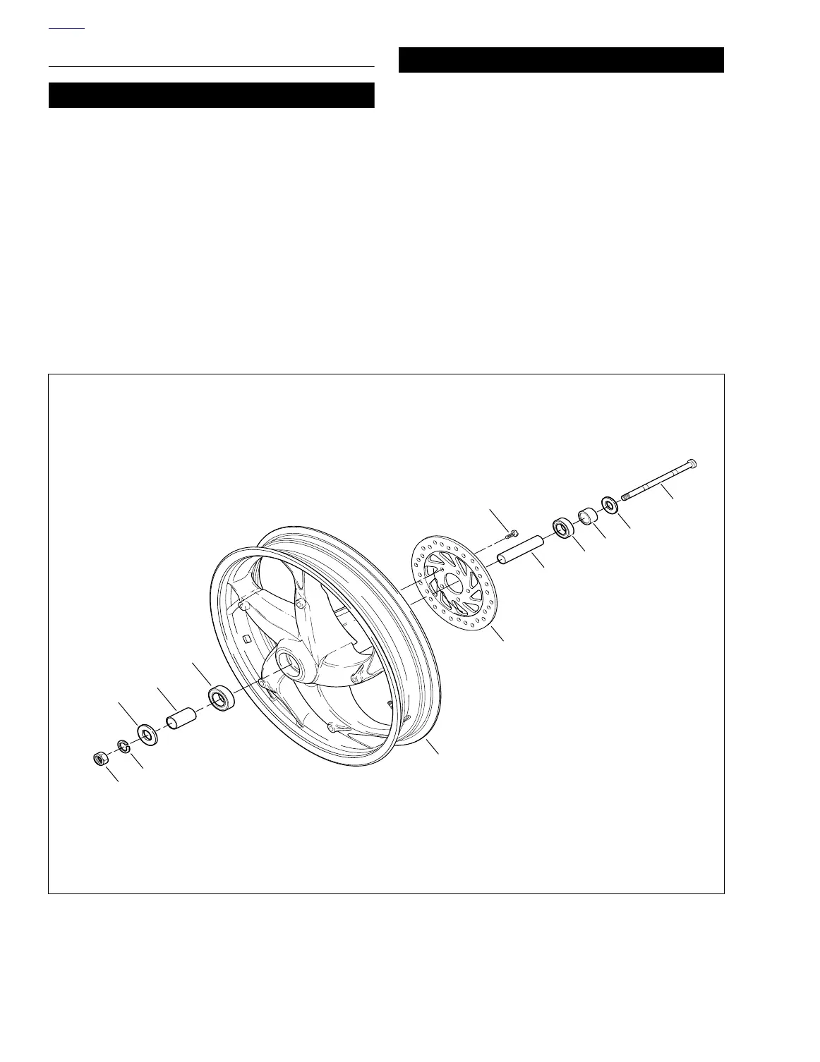
5. See Figure 2-9. Install brake rotor (9) to wheel.
a. Verify that the brake rotor is thoroughly clean.
b. Apply LOCTITE THREADLOCKER 272 (red) to
threads of each of the five T40 TORX screws (8).
c. Install rotor (9) on wheel hub. Tighten TORX screws
in criss-cross pattern to 24-27 ft-lbs (33-37 Nm).
Figure 2-9. Rear Wheel Assembly
2
4
7
5
3
9
6
12
1
8
10
1. Nut (metric)
2. Left axle spacer
3. Wheel bearing (left side)
4. Wheel
5. Axle spacer, center
6. Wheel bearing
7. Rear axle
8. Brake rotor screw (5)
9. Rear brake rotor
10. Right axle spacer
11. Lockwasher
12. Right axle spacer
a0079x2x
11
11