1110 - 31
DIGITAL INDUSTRIAL CONTROLLER
english
Function block 14: Manual controlled variable adjustment
This functional block can be activated at the Process Operation level. The manual
variable setting is only possible in the MANUAL operating mode of the unit. The
control element is switched out by the controller, and driven with the last-calculated
set variable. The value can now be changed using the “arrow” keys (See Par. 6.3).
Function block 15: Continuous signal
The controlled variable CO is output as a continuous signal Ra (see Figure 6, for
example). Three standard signals can be selected:
• Standard signal 0...10 V
• Standard signal 0...20 mA
• Standard signal 4...20 mA
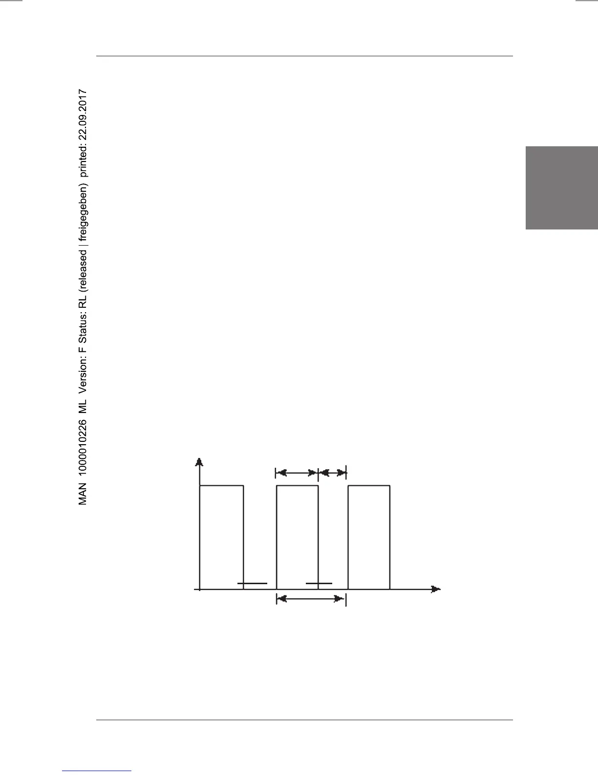
Function block 16: 2-point PWM signal
2-point output
When using a switching output, such as the 2-point PWM output, the continuous
variable CO, which is calculated by the PID algorithm, must be converted into a
switching signal.
This conversion takes place via a PWM element (PWM: Pulse-Width Modulation).
The relay will be clocked with a changeover period which is proportional to CO. In
this way, a quasi-continuous behaviour is achieved. The period T+ of the PWM
signal must be adapted to the regulated system.
Figure 18: 2-point PWM signal
CO = t
on
/ T+ *100%
t
on
= CO / 100 % T+
Relay on
t
ton / T+ ~ CO
Ra
Relay off
0
ton
toff
T+

 Loading...