6 - 1110
DIGITAL INDUSTRIAL CONTROLLER
english
The controller was conceived for installation in switch panels. On the controller,
first of all remove the retaining elements engaged on both sides by swivelling in
anticlockwise direction. Insert the controller, including the enclosed rubber seal, into
the insertion opening from the front. Then again engage the two retaining elements
in the bolts on the sides of the housing and screw in the threaded pin inside from the
rear.
Switch panel insertion opening (W x H): 92 x 92 mm
2
(+0,8 mm)
Outer controller dimensions (W x H x D): 96 x 96 x 173 mm
3
Controller weight: 960 g
Degree of protection: IP 65 (front when using the
enclosed seal)
Operating temperature: 0 bis +50 °C
Storage temperature: -20 bis +60 °C
3 INSTALLING THE CONTROLLER
ATTENTION!
To ensure the electromagnetic compatibility (EMC) the screw
terminal TE (Technical Earth) must be connected to the earth
potential by a cable that is as short as possible (30 cm, 2.5 mm
2
)
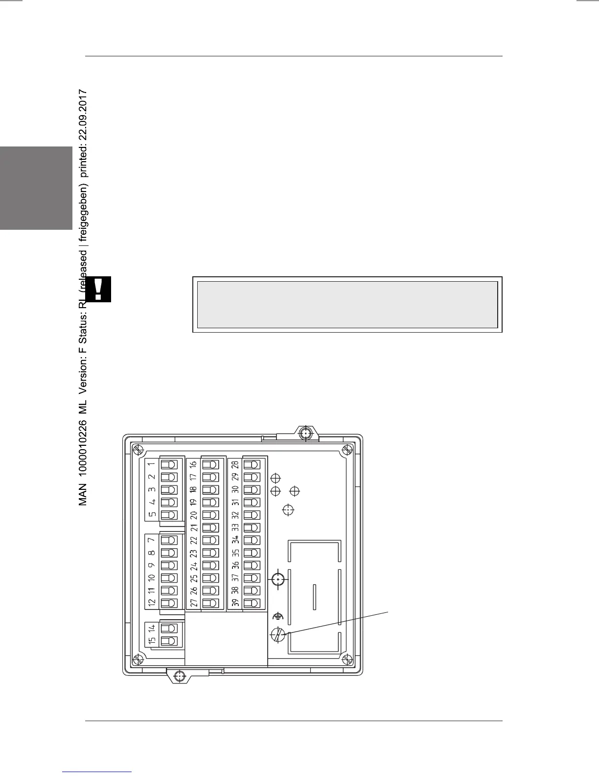
4 CONNECTIONS
Figure 2: Rear side of controller
4.1 Pin assignments
TE connection
(Technical Earth)

 Loading...


