1110 - 41
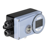
DIGITAL INDUSTRIAL CONTROLLER
english
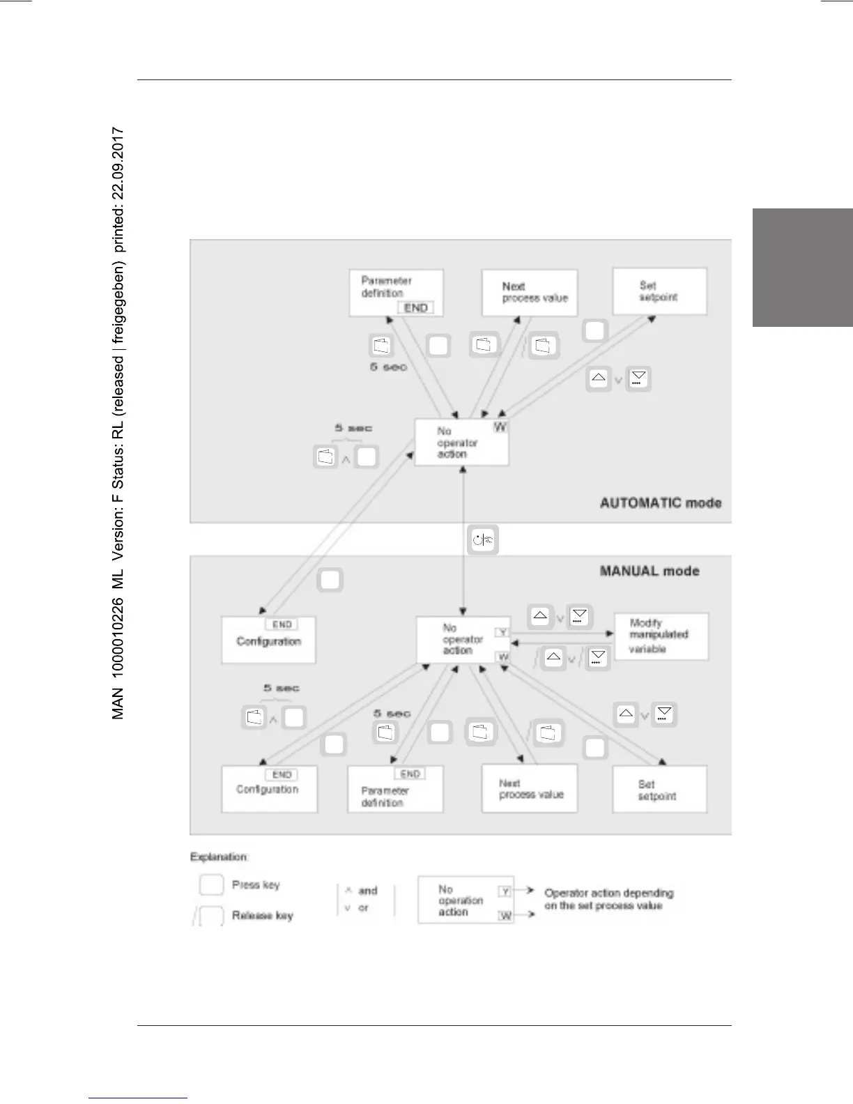
In the form of a flow chart, Figure 24 shows the meanings of the operator controls in
the
process operation
level. It is assumed that the controller is in one of the modes,
i.e. MANUAL or AUTOMATIC. Switching to the next process value by pressing the
DISPLAY key and setting the setpoint by pressing the „Up arrow“ and „Down arrow“
keys are possible both in MANUAL and AUTOMATIC mode. The manipulated varia-
ble can only be modified in MANUAL mode.
Figure 24: Flow chart of the process operation level
➤
➤
SELECT
ENTER
DISPLAY
DISPLAY
ENTER
SELECT
ENTER
0.....9 0.....9
➨
0.....9 0.....9
➨
0.....9 0.....9
➨
0.....9
0.....9
➨
ENTER
SELECT
ENTER
SELECT
ENTER
ENTER
DISPLAY
DISPLAY
ENTER

 Loading...