19
Installation
10.4 Installation on process valves, series
26xx and 27xx
Theinstallationoftheswitchspindleisdescribedinthe
operatinginstructionsfortype8692/8693.Youcannd
theinstructionsontheBürkerthomepage.
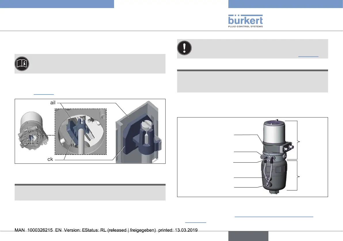
→ Placetype8692/8693ontotheactuator.Indoingso,alignthe
puckoftheactuatorwiththeguiderailoftype8692/8693
(see“Fig.10”).
Guiderail
Puck
Fig. 10: Aligning the puck
NOTE
Damage to the PCB or malfunction.
▶ Ensurethatthepuckliesatontheguiderail.
→ Presstype8692/8693allthewaydownasfarastheactuator
andturnitintotherequiredposition.
Ensurethatthepneumaticconnectionsoftype
8692/8693andthoseofthevalveactuatoraresituated
preferablyverticallyoneabovetheother(see“Fig.11”).
NOTE
To comply with the degree of protection IP65 / IP67, do not
fasten the fastening screws too tightly.
▶ Maximumtighteningtorque:1.5Nm(1.1Ibfft).
→ Attachtype8692/8693totheactuatorusingthetwosidefas-
teningscrews.Indoingso,tightenthescrewsonlyhand-tight
(max.tighteningtorque:1.5Nm(1.1Ibfft)).
Pilot air outlet 2
1
Pilot air outlet 2
2
Upperpilotairport
Lower pilot air port
Fastening screws
max.1.5Nm
(1.1Ibfft)
Type
8692/
8693
Actuator
Fig. 11: Installation of the pneumatic connections, series 26xx and 27xx
→ Observethepneumaticconnectionthatmatchesthedesired
controlfunction.See“Tab.2:Pneumaticconnectionto
actuator”.
english
Type 8692, 8693 REV.2
 Loading...


