25
Electrical installation
11.3 Electrical installation with cable gland
WARNING
Risk of injury from improper installation.
▶ Installationmaybecarriedoutbyauthorizedtechnicians
onlyandusingtheappropriatetools.
Risk of injury from unintentional activation of the system and
uncontrolled restart.
▶ Securesystemagainstunintentionalactivation.
▶ Followinginstallation,ensureacontrolledrestart.
DANGER
Risk of injury due to electric shock.
▶ Beforereachingintothesystem,switchothepowersupply
andsecuretopreventreactivation.
▶ Observetheapplicableaccidentpreventionregulationsand
safetyregulationsforelectricalequipment.
Procedure:
→ Loosenthe4screwsoftheconnectioncoverandremovethe
cover.Theconnectionterminalsarenowaccessible.
→ Pushthecablesthroughthecablegland.
→ Connectthewires.Theterminalassignmentcanbefoundin
thetablesbelow.
→ Tightentheunionnutofthecablegland(tighteningtorque
approx.1.5Nm(1.1Ibfft)).
→ Placetheconnectioncoverwithinsertedsealontotheelec-
tricalconnectionhousingandtightencross-wise(tightening
torquemax.0.7Nm(0.5Ibfft)).
NOTE
Damage or malfunction due to ingress of dirt and moisture.
To comply with the degree of protection IP65 / IP67:
▶ Closeallunusedcableglandswithdummyplugs.
▶ Tightentheunionnutonthecablegland.
Tighteningtorquedependsoncablesizeordummyplug
approx.1.5Nm(1.1Ibfft).
▶ Onlyscrewonconnectioncoverwiththesealinserted.
Tighteningtorquemax.0.7Nm(0.5Ibfft).
Whentheoperatingvoltageisapplied,type8692,8693is
operating.
→ Nowmaketherequiredbasicsettingsandadjustmentsfor
thepositioncontrollerandprocesscontroller.
Theprocedureisdescribedinchapter“12Start-up”.
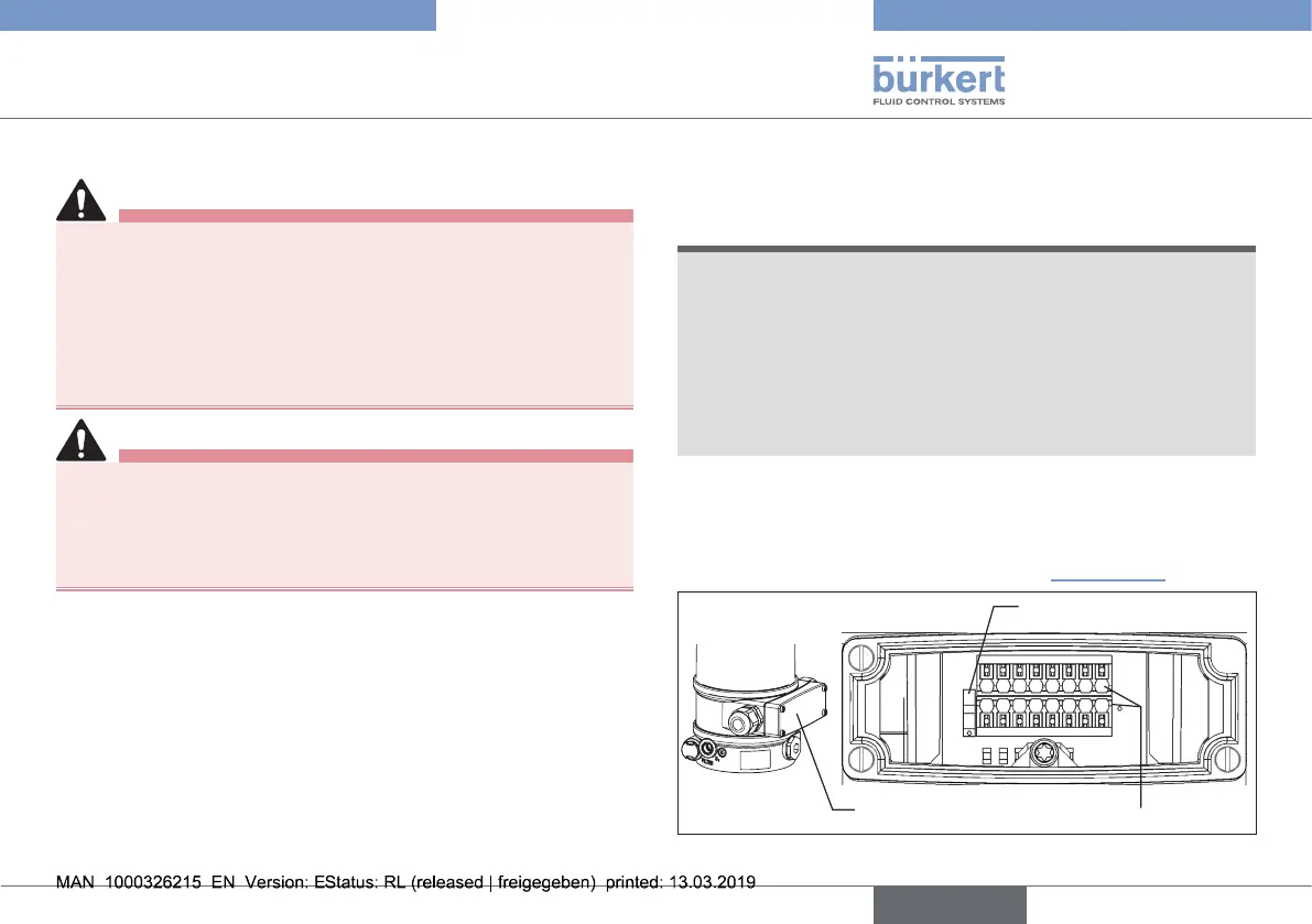
Connectioncover
Connectionterminals
Switch
1
2 3
1611
87
10
12
4
6
14
9
13
15
5
Fig. 14: Cable gland connection
english
Type 8692, 8693 REV.2