23
Electrical installation
11.2 Electrical installation with circular
plug-in connector
Procedure:
→ Connecttype8692/8693accordingtothetables.
Whentheoperatingvoltageisapplied,type8692/8693is
operating.
→ Nowmaketherequiredbasicsettingsandadjustmentsfor
thepositioner/processcontroller.FordescriptionseeChapter
“12.2Start-uptype8692”,page28.
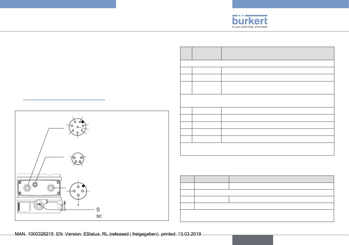
Designation of the circular plug-in connectors:
X6 - M12 circular connector,
4-pole
Operatingvoltage
X1 - M12 circular connector,
8-pole
Inputsignalsforthecontrol
center
Outputsignalsfromthe
controlcenter(optional)
Switch(tooperateloosenthe
screwconnection)
1
2
3
4
5
6
7
8
1
2
3
4
1
24
3
X5 - M8 circular connector,
4-pole (only Type 8693)
Input signals process actual
value
Fig. 13: Electrical connection with 24 V DC circular plug-in connector
X1 - M12 circular connector, 8-pole
Pin Wire
color*
Assignment
Input signals of the control centre (e.g. PLC)
1 white Digital input +
8 red
Set-pointvalue+ (0/4...20mA/0...5/10V)
7 blue Set-point
valueGND
Output signals to the control centre (e.g. PLC)
(required for analogue output and/or binary output option only)
2 brown
DigitaloutputsGND
3 green Digital output 2
4 yellow Digital output 1
5 gray
AnalogpositionfeedbackGND
6 pink Analogpositionfeedback+
* The indicated colors refer to the connection cable available as an
accessory (919061).
Tab. 3: X1 - M12 circular connector, 8-pole
X6 - M12 circular connector, 4-pole
Pin Wire color* Assignment
1 brown
Operatingvoltage+ 24 V DC
2
Notassigned
3 blue Operatingvoltage GND
4
Notassigned
* The indicated colors refer to the connection cable available as an
accessory (918038).
Tab. 4: X6 - M12 circular connector, 4-pole (operating voltage)
english
Type 8692, 8693 REV.2