36
büS OPTION
14.3 Electrical installation - büS
DANGER
Risk of injury due to electric shock.
▶ Beforereachingintothesystem,switchothepowersupply
andsecuretopreventreactivation.
▶ Observetheapplicableaccidentpreventionregulationsand
safetyregulationsforelectricalequipment.
WARNING
Risk of injury from improper installation.
▶ Installationmaybecarriedoutbyauthorizedtechnicians
onlyandwiththeappropriatetools.
Risk of injury from unintentional activation of the system and
uncontrolled restart.
▶ Securesystemagainstunintentionalactivation.
▶ Followinginstallation,ensureacontrolledrestart.
14.3.1 Electrical connection
X3-circularplug-inconnectorM12x1,5-pole,male:
Pin Wire color Assignment
1
CANshield CANshield
2 Notassigned
3 Black BlackGND/CAN_GND
4 White WhiteCAN_H
5 Blue BlueCAN_L
Tab. 16: Connection of the circular plug-in connector
X6-M12circularconnector,4-pole:
Pin Wire color* Assignment
1 brown
Operatingvoltage+24VDC
2 Notassigned
3 blue OperatingvoltageGND
4 Notassigned
*Theindicatedcolorsrefertotheconnectioncableavailableasan
accessory(918038).
Tab. 17: X6 - M12 circular connector, 4-pole (operating voltage)
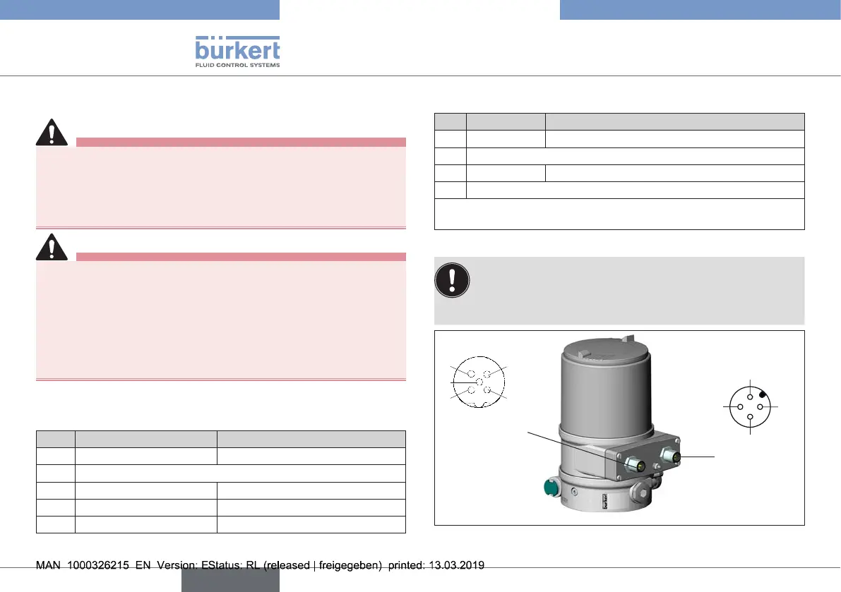
Electrical installation with or without büS network:
TobeabletousethebüSnetwork(CANinterface),a
5-polecircularconnectorandashielded5-wirecable
mustbeused.
X3 - 5-pole
M12 plug
1
2
3
4
5
X6 - M12
circular con-
nector, 4-pole
(operating
voltage)
1
2
3
4
Fig. 18: 5-pole M12 plug (example type 8693)
english
Type 8692, 8693 REV.2