24
Electrical installation
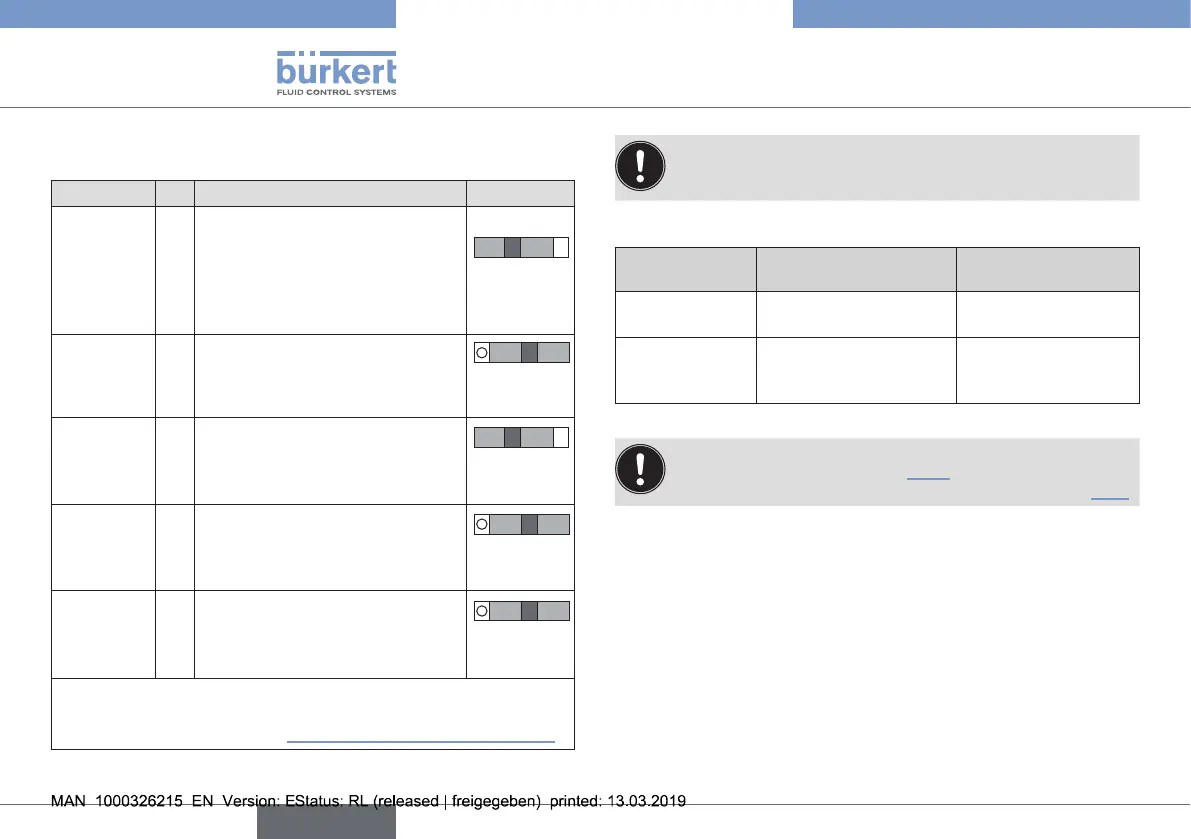
X5 - M8 circular connector, 4-pole -
(fortype8693only)
Input type* Pin Assignment Switch **
4...20mA
-internally
supplied
1
+24Vtransmitterpowersupply
Switchon
left
2
Outputfromtransmitter
3 GND(identicaltoGND
operatingvoltage)
4 BridgetoGND(GNDfrom
3-conductortransmitter)
4...20mA
-externally
supplied
1
Notassigned
Switchon
right
2 Process actual +
3
Notassigned
4 Process actual–
Frequency
-internally
supplied
1 +24 V sensor power supply
Switchon
left
2
Clockinput+
3 Clockinput–(GND)
4 Notassigned
Frequency
-externally
supplied
1
Notassigned
Switchon
right
2
Clockinput+
3 Clockinput–
4 Notassigned
Pt 100
(seeinfor-
mation
below)
1
Notassigned
Switchon
right
2 Process actual
1(powersupply)
3 Process actual3(GND)
4 Process actual2(compensation)
* Adjustable via software (see operating instructions type
8692/8693 Rev.2 “Setting the input signal”).
** Position of the switch, see “Fig. 14: Cable gland connection”.
Tab. 5: X5 - M8 circular plug, 4-pole, input signals process actual value
For reasons of wire resistance compensation, connect
the Pt 100 sensor via 3 wires.
Bridge Pin 3 and Pin 4 on the sensor.
11.2.1 Slide switch position
Supplied Assignment Slide switch
position
Internally
supplied
GNDoperatingvoltage Slideswitchonleft
Externally
supplied
GNDisgalvanically
isolatedfromthe
operatingvoltage.
Slideswitchonright
Tab. 6: Slide switch position
ThedescriptionEtherNet/IP,PROFINETandModbus
TCPcanbefoundinchapter“13”.
ThedescriptionoptionbüScanbefoundinchapter“14”.
english
Type 8692, 8693 REV.2
 Loading...


