22
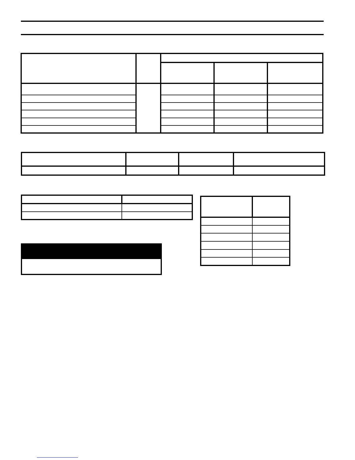
Table 6: Vent System and Combustion Air System Components
Vent System Component Equivalent Length (Ft.)
Schedule 40 CPVC Pipe x 30 Inches 2.5
Schedule 80 CPVC 90° Elbow 5
Combustion Air
System Component
(Parts by Others)
Equivalent
Feet of Pipe*
Pipe x 1 Ft. 1
Pipe x 2 Ft. 2
Pipe x 4 Ft. 4
Pipe x 5 Ft. 5
Elbow 5
Elbow 2.5
*Equivalent Feet of Pipe Based on
Standard 4” PVC Design
Table 5: Clearances from Vent Piping to Combustible Material
Vent Pipe Pipe Direction Enclosure
Minimum Clearance To
Combustible Material
CPVC/PVC Venting Vertical or Horizontal Enclosed at all Sides See Figures 2A and 2B
Vent Components
Part
Number
Quantity
ALP080 & A
LP105
Horizontal (Snorkel)
Termination
ALP150& A
LP210
Horizontal (Snorkel)
Termination
ALP285 thru ALP500
Horizontal (Snorkel)
Termination
3" Schedule 40 PVC Pipe x up to 7 ft. max. vertical run
N/A
Supplied by
Others
2 1 N/A
4" Schedule 40 PVC Pipe x up to 7 ft. max. vertical run N/A 1 2
3" Schedule 40 PVC 90° Elbow
4 2 N/A
4" Schedule 40 PVC 90° Elbow
N/A 2 4
3" Schedule 40 PVC Pipe x ½ ft. min. horizontal run
2 1 N/A
4" Schedule 40 PVC Pipe x ½ ft. min. horizontal run
N/A 1 2
Table 4C: CPVC/PVC Vent & Air Intake Components (Installer Provided) required for Optional Horizontal
(Snorkel) Termination
WARNING
All condensate that forms in the vent must be
able to drain back to the boiler.
b. V
ent length restrictions are based on equivalent
length of vent/combustion air pipe (total length
of straight pipe plus equivalent length of
ttings). Maximum vent/combustion air lengths
are listed in Table 7. Do not exceed maximum
vent/combustion air lengths. Table 6 lists
equivalent lengths for ttings. Do not include
vent/combustion air terminals in equivalent
feet calculations. See “Combustion Air/Vent,
Equivalent Length Work Sheet”.
c. The vent termination location is restricted as per
'General Guidelines', Paragraph A, 5.
(Refer to Figure 3).
2. System Assembly
a. Plan venting system to avoid possible contact
with plumbing or electrical wires. Start at
vent connector at boiler and work towards vent
termination.
b. Do not exceed maximum Vent/Combustion Air
length. Refer to Table 7.
c. Design the Vent System to allow 3/8" of thermal
expansion per 10 feet of CPVC/PVC pipe. Runs
of 20 feet or longer that restrained at both ends
must use an offset or expansion loop. Refer to
Figure 4.
d. Follow all manufacturer instructions and
warnings when preparing pipe ends for joining
and using the primer and the cement.
3. Field Installation of CPVC/PVC Two-Pipe
Vent System Connector - Floor Mounted
Boiler Builds
Refer to Figure 5 and Steps below:
a. Position the CPVC/PVC vent connector and
gasket onto boiler rear/bottom panel and insert
vent connector inner stainless steel vent pipe into
heat exchanger vent outlet.
b. Align vent connector plate and gasket clearance
holes with rear/bottom panel engagement holes;
than, secure the connector and gasket to the
panel with six mounting screws.
IV. Venting (continued)