66
e. Individual module (boiler) sidewall concentric
vent terminals must be placed at least twelve
(12) inches above the ground plus the expected
snow accumulation.
f. For vertical through the roof venting any
adjacent individual module (boiler) vertical
vent terminals, if level with each other, must be
spaced no closer than 12 inches horizontally.
If vertical vent terminals cannot end in one
plane, they must be spaced no closer than three
(3) feet horizontally.
g. Chimney chase concentric venting is permitted
for modules, when stackable, providing
concentric vertical (roof) vent terminals, if level
with each other, are spaced no closer then 12
inches horizontally.
If vertical vent terminals cannot end in one
plane, they must be spaced no closer then three
(3) feet horizontally.
h. When individual modules (boilers) are installed
in the same horizontal plane, chimney chase
vertical concentric venting is permitted provided:
i. Sufcient inside space available at the base
of the chimney to install multiple chimney
chase brackets and support elbows.
ii. Spacing between adjacent vertical vent
terminals is in accordance with paragraph g
above.
CAUTION
Installing multiple individual module (boiler)
concentric vent terminations too close together
may result in combustion product water vapor
condensation on building surfaces, where
termination are placed, and subsequent frost
damage. To avoid/minimize frost damage extend
the distance from building surfaces to concentric
vent termination end as well as increase the
horizontal distance between adjacent concentric
vent terminations.
C. Water Piping – (See Table 20 and Figure 41)
1. Refer to Section VI “Water Piping and Trim” of this
manual for:
a. Installation of Factory Supplied Piping and
Trim
Components for an individual module (boiler).
b. Regarding an individual module (boiler) piping
system specic details.
c. Selection criteria for individual module (boiler)
space heating and/or DHW circulators.
2. For installations where indirect domestic hot water
heater is combined with space heating, when sizing
an indirect water heater circulator
, compare the
specied ow range through an Alpine model boiler
to an indirect water heater (Alliance SL™) model
coil ow rate required to achieve water heater
rating. Refer to Table 21.
a. When Alliance SL™ model coil ow rate,
required to achieve water heater rating, falls
within the specied ow range for Alpine
boiler model, the Alliance SL™ model can be
piped as part of Alpine near-boiler piping.
Refer to Table 21.
b. When Alliance SL™ model coil ow rate,
required to achieve water heater rating,
exceeds the specied ow range for Alpine
boiler model, the Alliance SL™/Alpine boiler
combination may result in excessive noise and
boiler heat exchanger erosion, and therefore,
is not recommended. Refer to Table 21 for
details.
c. When Alliance SL™ model coil ow rate,
required to achieve water heater rating, falls
below the specied ow range for Alpine boiler
model, the Alliance SL™ model must be piped
as a separate heating zone off the system
header. The circulator must be sized based on
the Alliance SL™ model coil ow and combined
coil pressure drop and the zone piping total
equivalent length. Refer to Table 21 for details.
D. Gas Piping
1. Individual module (boiler) gas pipe sizing specic
details
2. Individual module (boiler) recommended gas piping.
See Figure 34A.
3. Requirement to install additional gas pressure
regulators to properly regulate gas pressure at the
input of the smallest individual module (boiler).
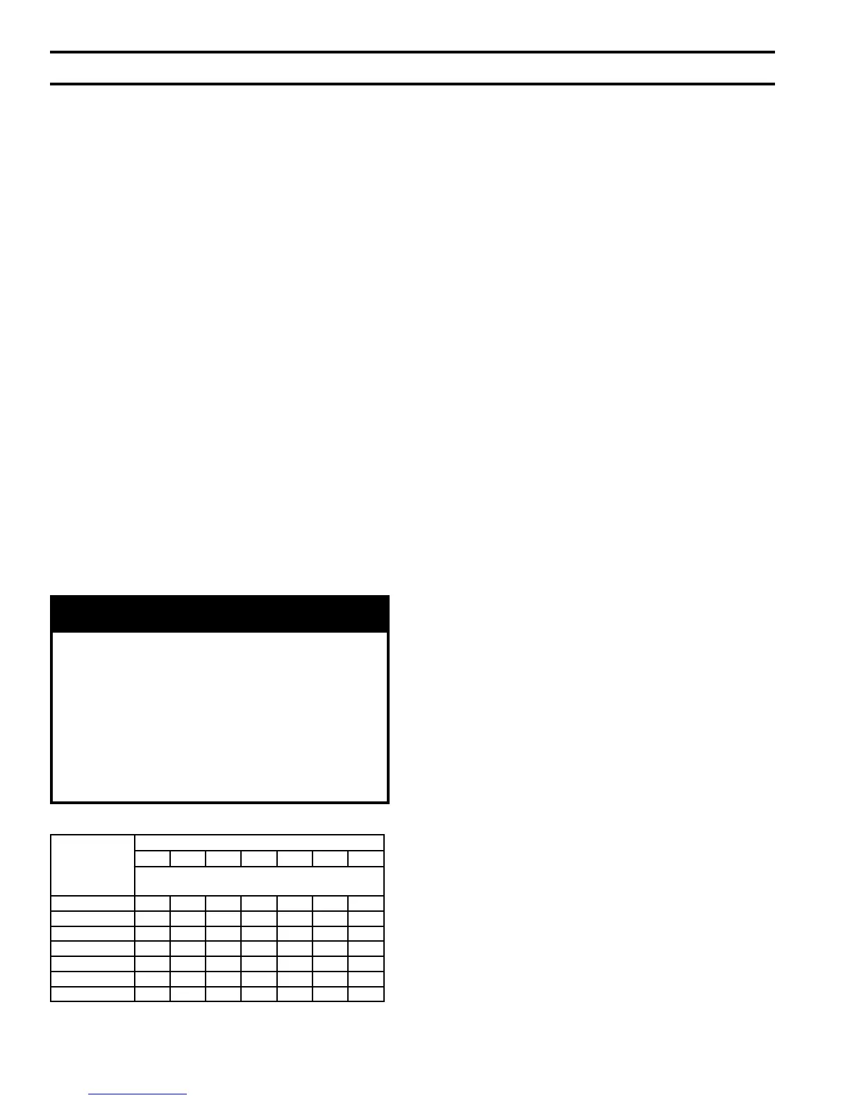
T
able 20: Modular Boiler Water Manifold Sizing
Boiler Model
Number of Units
2 3 4 5 6 7 8
Recommended Minimum Common Water
Manifold Size (N
PT)
ALP080 1¼” 1½” 1½” 2” 2” 2” 2½”
ALP105 1¼” 1½” 2” 2” 2½” 2½” 2½”
ALP150 1½”
2” 2½” 3” 3
” 3” 3”
ALP210 2” 2½” 2½” 3” 3
½” 3½” 3½”
ALP285 2” 3” 3
” 3½” 4” 4” 5”
ALP399 2½” 3” 3
” 4” 5” 5” 5”
ALP500 3” 4” 4” 5” 5” 6” 6”
X. Modular Installation (continued)