30
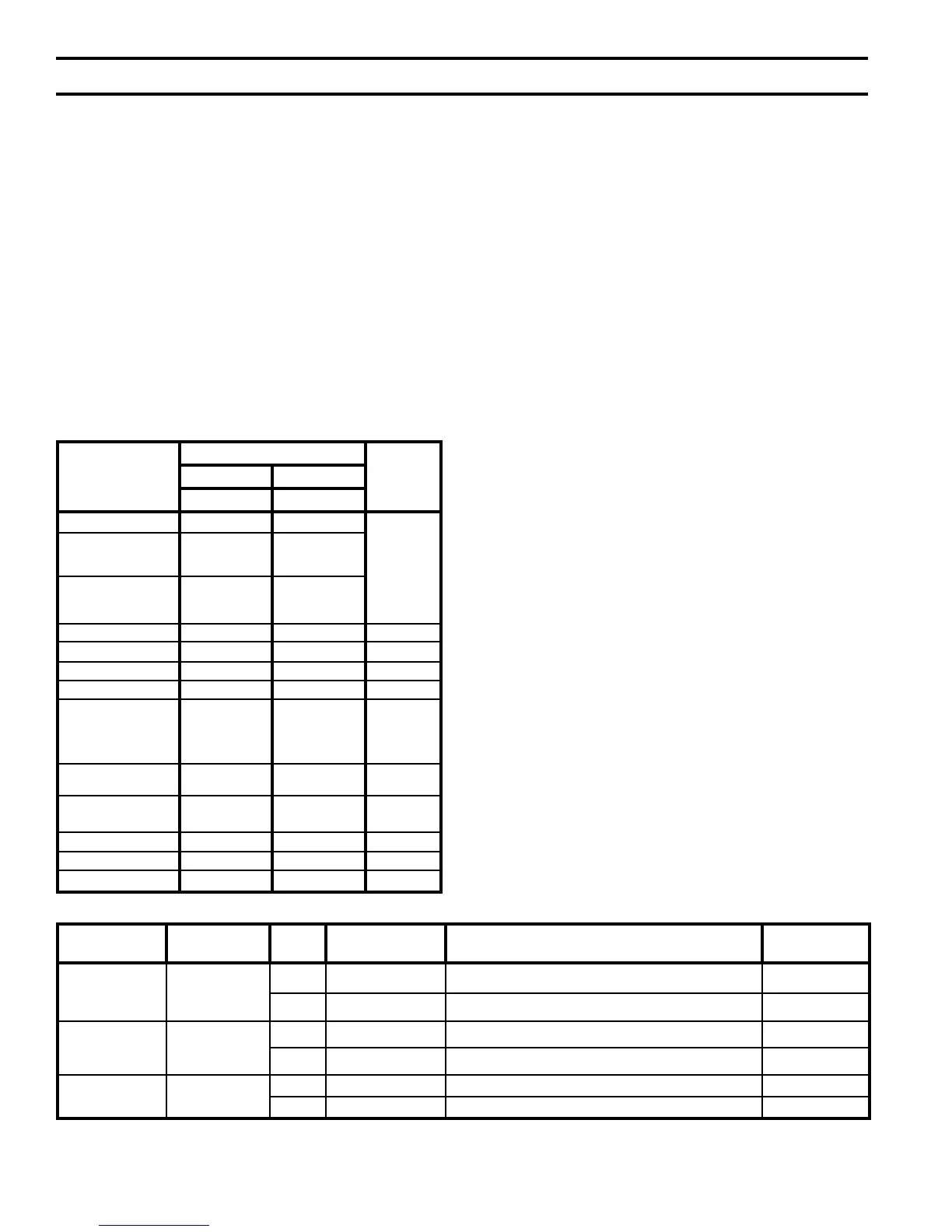
Vent System
Component
Part Numbers
Equivalent
Feet of Pipe
ALP080 - 210 ALP285 - 500
3" Vent 4" Vent
SS Vent Kit 102501-01 102501-02
N/A
Horizontal Vent
Terminal
(Included in Kit)
8116310 8116313
PVC to SS Vent
Adapter
(Included In Kit)
102219-01 102220-01
Vertical Vent Terminal 102680-01 102680-02 N/A
Pipe x 1 Ft. 8116296U 100176-01 1
Pipe x 3 Ft. 8116298U 100177-01 3
Pipe x 5 Ft. 8116300U 100178-01 5
Pipe x Adjustable 8116319U 100179-01
Equal to
Installed
Length
(1.06 to 1.64)
90° Elbow 8116294U 100180-01
5.5 (3")
8.0 (4")
45° Elbow 8116292U 100181-01
4.0 (3")
4.5 (4")
Horizontal Drain Tee 8116302U 100182-01 2
Vertical Drain Tee 8116304U 100183-01 7½
Single Wall Thimble 8116116 100184-01 N/A
Table 8A: U.S. Boiler Vent System Components
(Stainless Steel)
IV. Venting (continued)
Manufacturer
Vent
System
Size Wall Thimbles Horizontal Termination
Vertical
Termination
Protech
Systems
Inc..
FasNseal
3 FSWT3 Tee: FSTT3 FSBS3
4 FSWT4 Tee: FSTT4 FSBS4
Z-Flex
SVE
Series III
(“Z-Vent III”)
3 2SVSWTEF03 Tee: 2SVSTTF03 24SVSTPF03
4 2SVSWTEF04 Tee: 2SVSTTF04 24SVSTPF04
Flex-L Intl. Star-34
3 SR03WT15 Tee: SRTT-03 SRTP-03
4 SR04WT15 Tee: SRTT-04 SRTP-04
NOTE: See vent system manufacturer’s literature for other part numbers that are required such as straight pipe, elbows, restops
and vent supports.
Table 8B: Alternate Vent Systems and Vent Components (Stainless Steel)
• Male end of terminal will t into the
female end of any of the approved
stainless vent systems.
• Apply a heavy bead of silicone to the
male
end of the terminal before inserting
it into the last piece of pipe. Orient the
terminal so that the seam in the terminal
is at 12:00.
• Smooth the silicone over the seam
between the terminal and the last piece
of pipe, applying additional silicone if
necessary to ensure a tight seal.
• Allow the silicone to cure per the
silicone manufacturer’s instructions
before operating the boiler.
ii. Combustion Air
Termination
• Horizontal intake terminal is a tee in the
upright position. Tee should protrude
the same distance from the wall as the
exhaust terminal. See Figure 8.
• Install a rodent screen (not supplied) in
the inlet terminal. Use a screen having
1/2”
(2 x 2) or larger mesh.
b. Optional Two-Pipe Snorkel Termination
Refer to Figure 10.
This installation will allow a maximum of
seven (7) feet vertical exterior run of the vent/
combustion air piping to be installed on the
approved AL29C Stainless Steel horizontal
venting application.
i. Vent Termination
• After penetrating wall, install the
appropriate manufacturer's 90° elbow so
that the elbow leg is in the up direction.
• Install maximum vertical run of seven
(7) feet of appropriate manufacturer's
vent pipe. See Figure 10.
• At top of vent pipe length install another
appropriate manufacturer's 90° elbow
so that the elbow leg is opposite the
building's exterior surface.
• Install horizontal vent terminal.
• Brace exterior piping if required.
ii. Combustion Air
Termination
• After penetrating wall, install a 90°
elbow so that the elbow leg is in the up
direction.
• Install maximum vertical run of seven
(7) feet of combustion air pipe. See
Figure 10.
• At top of vent pipe length install another
90° elbow os that the elbow leg is
opposite the building's exterior surface.