53
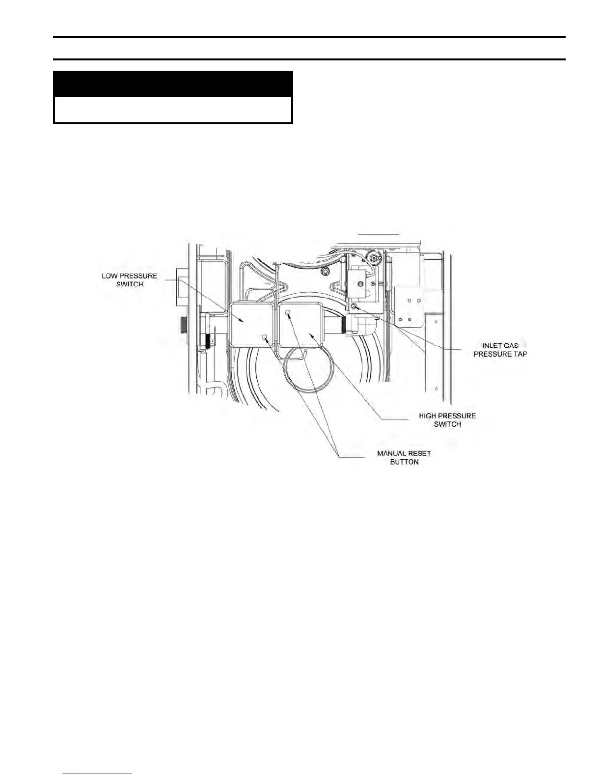
Figure 34B: Gas Inlet Pressure Switch Location
VII. Gas Piping (continued)
DANGER
Do not use matches, candles, open ames or
other ignition source to check for leaks.
D. Alpine Model 500 only (if equipped with optional low
and high gas pressure switches):
1. The low gas pressure switch must be reset after the
boiler is piped to the gas supply and before it is
red.
2. For the low and high gas pressure switches proper
operation, the boiler inlet gas pressure must be
within 4.5” w.c. to 13.5” w.c. range.
3. The gas pressure can be measured at the gas valve
inlet pressure port. Refer to Figure 34B.
4. If either pressure switch is tripped, it must be
manually reset before the boiler can be restarted.