5 | Installation
18 / 56 0870215096_RA0760A_PLUS_-0001_IM_en
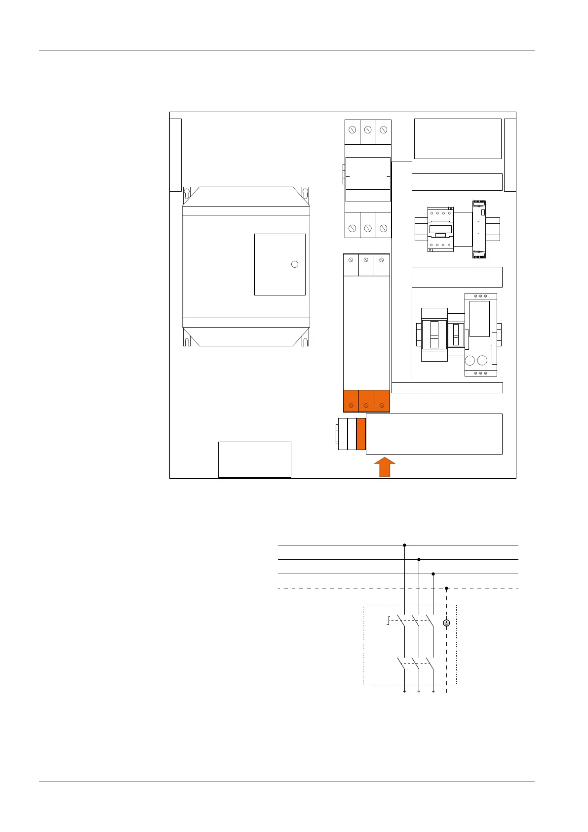
5.4.1 Wiring Diagram Control Unit
Internal view of the control unit:
VFD
U1
PE
V1
L1 L2 L3
X1
Q3
Q2
U2
B1 F1
KM1
PLC1
Q1
Power
input
Box fan
Filter
Box filter
Box filter
Customer power supply:
Power supply
3L+PE 400-460V +/-10%
50/60Hz
Lockable disconnect switch
Overload protection
C-curve - 80A
to the control unit
Must be provided by the customer
The complete wiring diagram of the control unit is
placed inside the electrical cabinet.
Wire gauge according to EN 60204-1
Cable gland size of the power input:
– M40 x 1.5 (cable Ø ► 20 … 33 mm)
 Loading...