2 | Product Description
8 / 56 0870215096_RA0760A_PLUS_-0001_IM_en
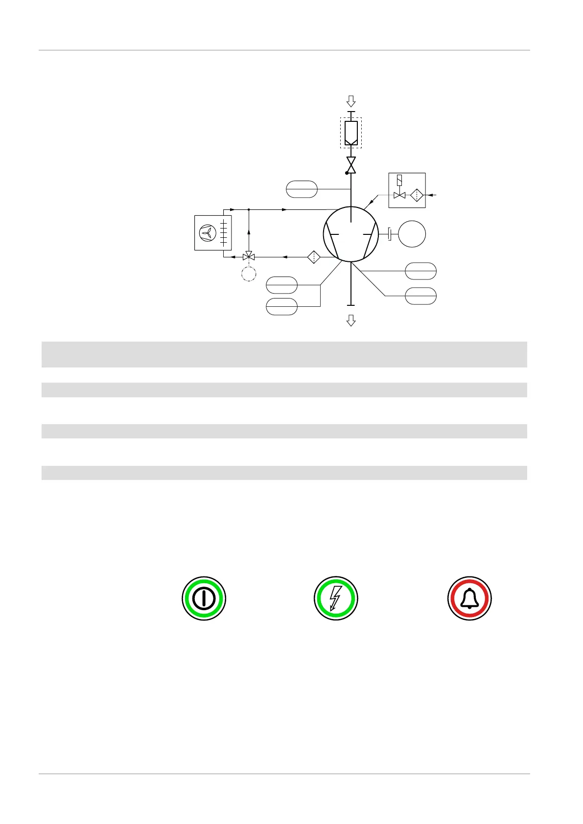
2.5 P&ID "Piping and Instrumentation Diagram"
PSA1
P
M
CPL
MOT1
G3
GB
Air
NRV
IF
inlet gas
LS
low oil level
alarm (trip)
PSA2
P
TSA
Toil
AHE
TTV
76°C
G3
IN
OUT
OF
TS
Texhaust gas
VP
exhaust gas
Optional
AHE Air-oil heat exchanger
(fan driven by the pump shaft)
CLP Coupling
GB Gas ballast IF Inlet filter (Optional)
IN Suction connection LS Level switch "alarm/trip” (oil level)
MOT1 Motor (pump drive) NRV Non-return valve
(not used as an isolation valve)
OF Oil filter OUT Discharge connection
PSA1 Pressure transmitter
(inlet gas pressure)
PSA2 Pressure transmitter
(counter pression in the oil separator)
TSA Resistance thermometer (oil temp.) TS Temperature switch (exhaust gas temp.)
TTV Three-way thermostatic valve VP Vacuum pump
2.6 LED Indicators
Next to the user interface, there are three LED’s which give a visual indication of the ma-
chine state.
The LED is green when
the machine is powered
The LED is green when
the machine is running
The LED flashes in red
when a warning occurred /
The LED is continuously
red when an alarm occurred
Power indicator light (PIL)Start/stop button (SSB) Alarm indicator light (AIL)
 Loading...