EasyManua.ls Logo

CAME FAST KIT User Manual

CAME FAST KIT
32 pages
To Next Page IconTo Next Page
Page #1 background imageLoading...
Page #1 background image
CAME UNITED KINGDOM LTD
UNIT 3,
ORCHARD PARK INDUSTRIAL ESTATE,
TOWN STREET, SANDIACRE,
NOTTINGHAM NG10 5BP
TEL: 0115 921 0430
FAX: 0115 921 0431
INTERNET - www.cameuk.com
E-MAIL - enquiries@cameuk.com
TECHNICAL
HELPLINE
0115 921 0430
FAST KIT
Installation Instructions
FAST-P, Pair of gates automation kit
Kit consists of :
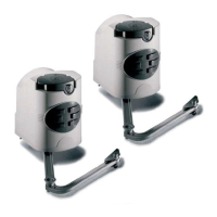
2 x fast motors 240V
1 x built-in control panel 240V
1 x radio receiver
1 x tuned antenna
2 x remote control handsets
1 x pair safety photocells
1 x flashing “in movement” light
Full installation guide
FAST-S, Single gate automation kit
Kit consists of :
1 x fast motor 240V
1 x built-in control panel 240V
1 x radio receiver
1 x tuned antenna
2 x remote control handsets
1 x pair safety photocells
1 x flashing “in movement” light
Full installation guide
UNITED KINGDOM LTD.
Questions and Answers:

CAME FAST KIT Specifications

General IconGeneral
BrandCAME
ModelFAST KIT
CategoryGarage Door Opener
LanguageEnglish

Summary

INTRODUCTION

Installation Type

Lists the components of the FAST gate automation kit.

1.1 - Requirements

EXTERNAL DIMENSIONS AND OPERATING LIMITS

Specifies the physical dimensions and weight limits for the gate wings.

BEFORE INSTALLING...

Crucial checks and measurements before starting installation.

1.2 - Mounting the Motor Base Plate

Front view

Illustrates the front view for base plate mounting with key dimensions.

STAGE 2 WIRING AND ELECTRICAL

2.1 - Basic Cable Layout

Illustrates the general layout for electrical cabling.

STAGE 3 INSTALLATION

3.1 - Installing the Motors

Instructions for physically installing the gate motors.

3.2 - Installing drive arms

Guidance on fitting the drive arms to the motors and gates.

3.3 - Adjusting the open and shut cams

How to set the limit switches for gate movement.

STAGE 4 WIRING THE MOTORS

4.1 - Electrical connections to the ZF1 board with pair of gates

Wiring instructions for a pair of gates to the control board.

4.2 - Electrical connections to the ZF1 board with single gate

Wiring instructions for a single gate to the control board.

4.3 - Electrical Connections

General guide to making electrical connections for the system.

STAGE 5 COMMISSIONING THE CONTROL PANEL

5.1 - Initial Wiring & Control Panel Set-Up

Initial wiring and configuration of the control panel.

5.2 - Opening & Closing the Gates

Steps to set the basic opening and closing operations.

5.3 - Control Panel Adjustments

Adjusting settings on the control panel for optimal performance.

5.4 - Automatic Close & Safety Photocells

Setting up automatic closing and safety photocells.

5.5 - Programming the Remote Controls to the Control Panel

Process for pairing remote controls with the system.

5.6 - Coding the Additional Remote

Instructions for coding extra remote controls.

5.7 - Final Assembly

Final steps for assembling the system components.

STAGE 6 TECHNICAL INFORMATION

6.1 - Electrical Connections

Detailed diagrams of electrical connections for the system.

6.2 - Function Selections

Explains how to select various functions of the control panel.

6.3 - Technical Description - ZF1 Control Panel

Technical specifications and description of the ZF1 control panel.

6.4 - Motherboard

Information about the motherboard and its components.

6.5 - Adjustments

Details on various adjustments and settings available.

7. TROUBLESHOOTING GUIDE

CONTACT INFORMATION

Related product manuals