EasyManuals Logo

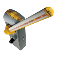
CAME GARD 4 SERIES User Manual

CAME GARD 4 SERIES
30 pages
To Next Page IconTo Next Page
To Previous Page IconTo Previous Page
Page #12 background imageLoading...
Page #12 background image
Page
12
12 - Manual code:
119 G U5 5
119 G U5 5 ver.
1.1
01/2012 © CAME cancelli automatici s.p.a. - The data and information in this manual may be changed at any time and without obligation on the part of Came Cancelli Automatici S.p.a. to notify said changes.
ENGLISH
- Release the gearmotor and position the arm vertically, then lock it back
into place.
- Prepare the spring by tightening the ring-bolt below. Thee
screw should then be fi tted onto the lug which is hooked to the
transmission arm.

Questions and Answers:

Question and Answer IconNeed help?

Do you have a question about the CAME GARD 4 SERIES and is the answer not in the manual?

CAME GARD 4 SERIES Specifications

General IconGeneral
Power Supply230V AC
Motor Power300W
Operating Temperature-20°C to +55°C
Protection RatingIP54
ModelGARD 4
TypeBarrier Gate
Boom Length4 meters

Related product manuals