01/2012
© CAME cancelli automatici s.p.a. - The data and information in this manual may be changed at any time and without obligation on the part of Came Cancelli Automatici S.p.a. to notify said changes.
ENGLISH
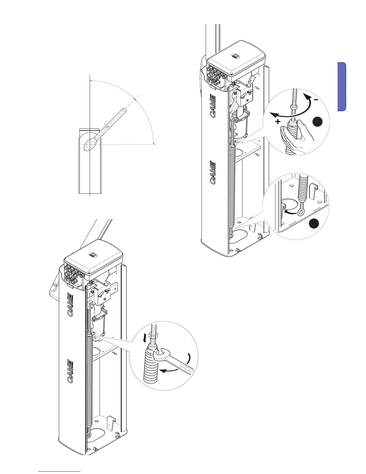
- Attach the ring-bolt to the anchoring bracket
release the gearmotor and manually turn the spring to increase or
decrease traction. The barrier arm must stabilise at 45°.
- Fit the counter nut and block the gearmotor back into place.
Note: Check proper working order of the spring:
- with barrier arm in vertical position, the spring is not
under tension.
- with barrier arm in horizontal position, the spring is
loaded.
- C
ARRY OUT THE ELECTRICAL CONNECTIONS ON CONTROL PANEL (SEE
ELECTRICAL CONNECTIONS PARAGRAPH).

 Loading...


