Chapter 7
7-12
b) I/O DISPLAY
The information of each sensor and switch is shown in the display.
Sensor and switch status is shown in the display.
ON=1 OFF or not used=0
ON = 1
OFF or not used = 0
Screen 1
T-7-9
Screen 2
T-7-10
Screens 1 and 2 are selectable with the [ ] and [ ] buttons.
These screens display the associated sensor status as listed in the table below.
T-7-11
I/O DISPLAY 1 Upper row
0000000000000000Lower row
12345678910111213141516(Display position)
I/O DISPLAY 2 Upper row
0000000000000000Lower row
17 18 19 20 21 22 23 24 25 26 27 28 29 30 31 32 (Display position)
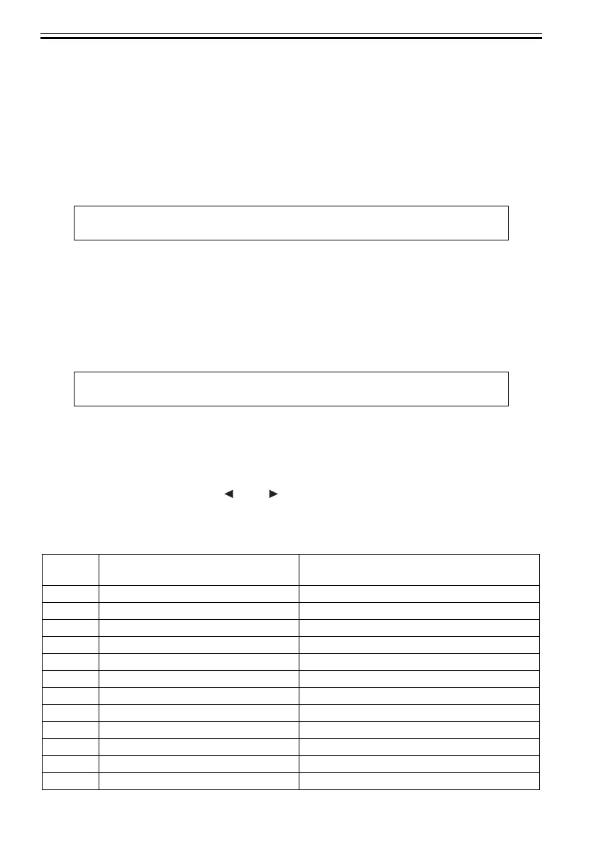
Display
position
Sensor name LCD display contents
1 Pump Cam Sensor 0: Sensor ON , 1: Sensor OFF
2 Valve Open/Closed Detection Sensor 0: Sensor ON , 1: Sensor OFF
3(Not Used) 0
4(Not Used) 0
5(Not Used) 0
6(Not Used) 0
7 Feed Roller HP Sensor 0: Sensor ON , 1: Sensor OFF
8 Upper Cover Lock Switch(L/R) 0: Cover open , 1: Cover close
9 Carriage Cover Sensor 0: Cover open , 1: Cover close
10 Ink Tank Cover Switch 0: Cover open , 1: Cover close
11 (Not Used) 0
12 (Not Used) 0