LASER CLASS 730i/720i/710 Chapter 5: Appendix
5-71
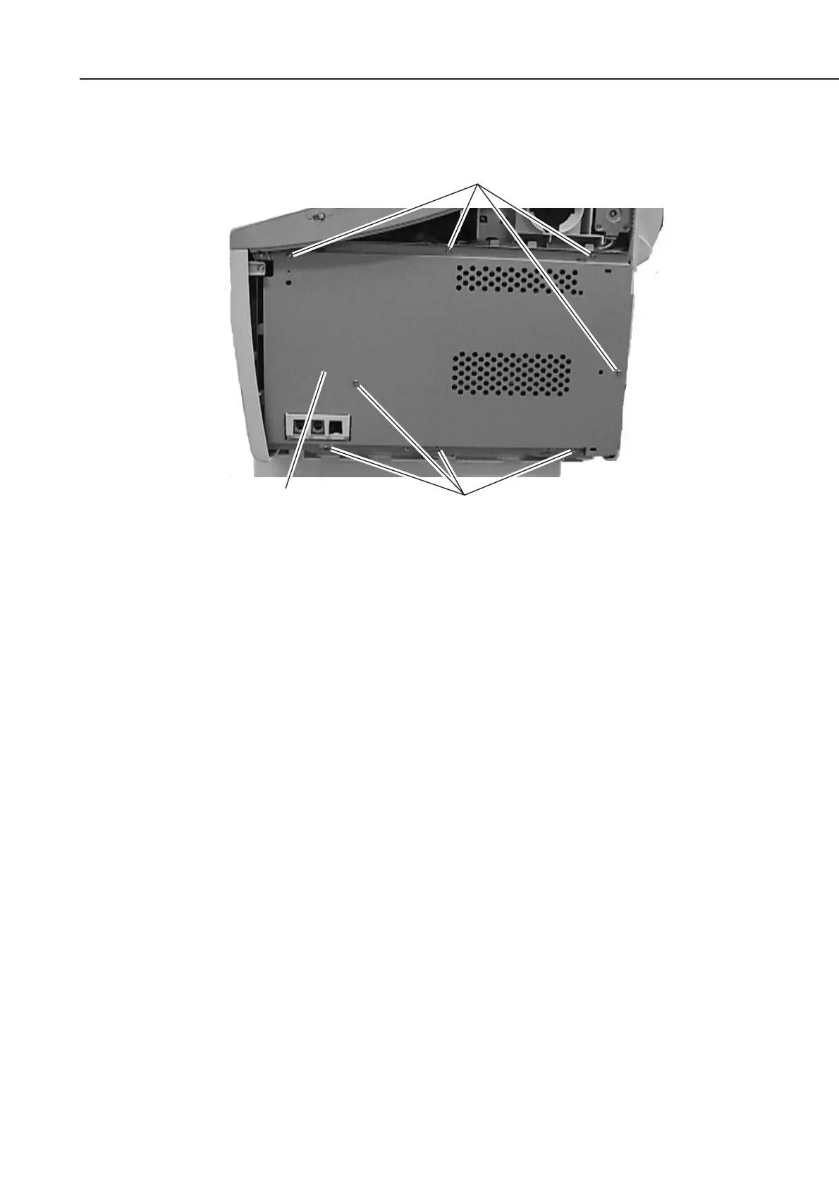
(4) Fasten the shield plate in place with the eight screws.
Figure 5-80 Printer Kit III Installation 3
(5) Fasten the right cover in place with the two screws.
(6) Connect the modular cord (telephone line) to the fax (L1 jack).
b-5) Check after the Kit Installation
After installing the kit, carry out the following procedure to ensure that the kit is properly
identified by the main unit.
(1) Connect the power supply cord to the main unit.
(2) Carry out COLD RESET by the following procedure in service mode.
Press the Data Registration button and the # button to go into service mode.
Press the Search button to display “#8 PDL” and press the Set button.
Press the Search button to display “PDL-PCL MENU” and press the Set button.
Press the Search button to display “COLD RESET LETTER” reset is carried out by
pressing the Set button. “READY” is displayed later on.
(3) Carry out COLD RESET again after ensuring the display “READY”.
(4) Output the TEST PRINT about the PCL board by the following procedure, and ensure
that the operation is done properly.
Press the PRT. Message button on the operation panel to light a lamp.
Press the Go button and the Menu button to display “TEST MENU”.
Select “TEST PRINT” by pressing the Item button, and press the Enter/Cancel button.
The TEST PRINT on which the state of the PCL board is printed is outputted if the kit
has been installed properly.
Screws
Screws
Shield plate