LASER CLASS 730i/720i/710 Chapter 5: Appendix
5-82
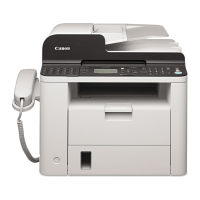
b-4) Attaching to the main unit
(1) When attaching the PCL unit, check to make sure that the core of the 10-pin cable must
be placed between the backside of the PCL unit and the cable clip. (Do not place the
core on the PCL unit board surface) After that, secure the PCL unit with six screws.
Figure 5-96 Network Kit III Installation 1
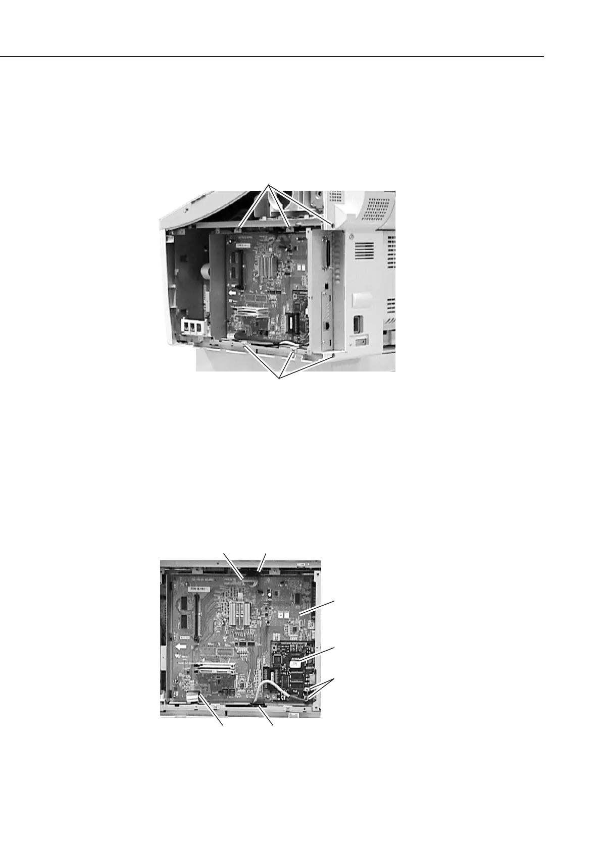
(2) Connect the flat cable to the connector J5 of the PCL board.
(3) Connect the 10-pin cable to the connector J6 of the PCL board, and then secure it in
place using clamp.
(4) Connect the 5-pin cable to the two connectors of the NIC board, and then secure it in
place using clamp.
Figure 5-97 Network Kit III Installation 2
Screws
Screws
Connector J5
PCL board
Clamp
NIC board
Connectors
(NIC board)
Connector J6 Clamp
manuals4you.commanuals4you.com