17
ENG
pCO5plus +0300020EN rel. 1.2 - 07.11.2013
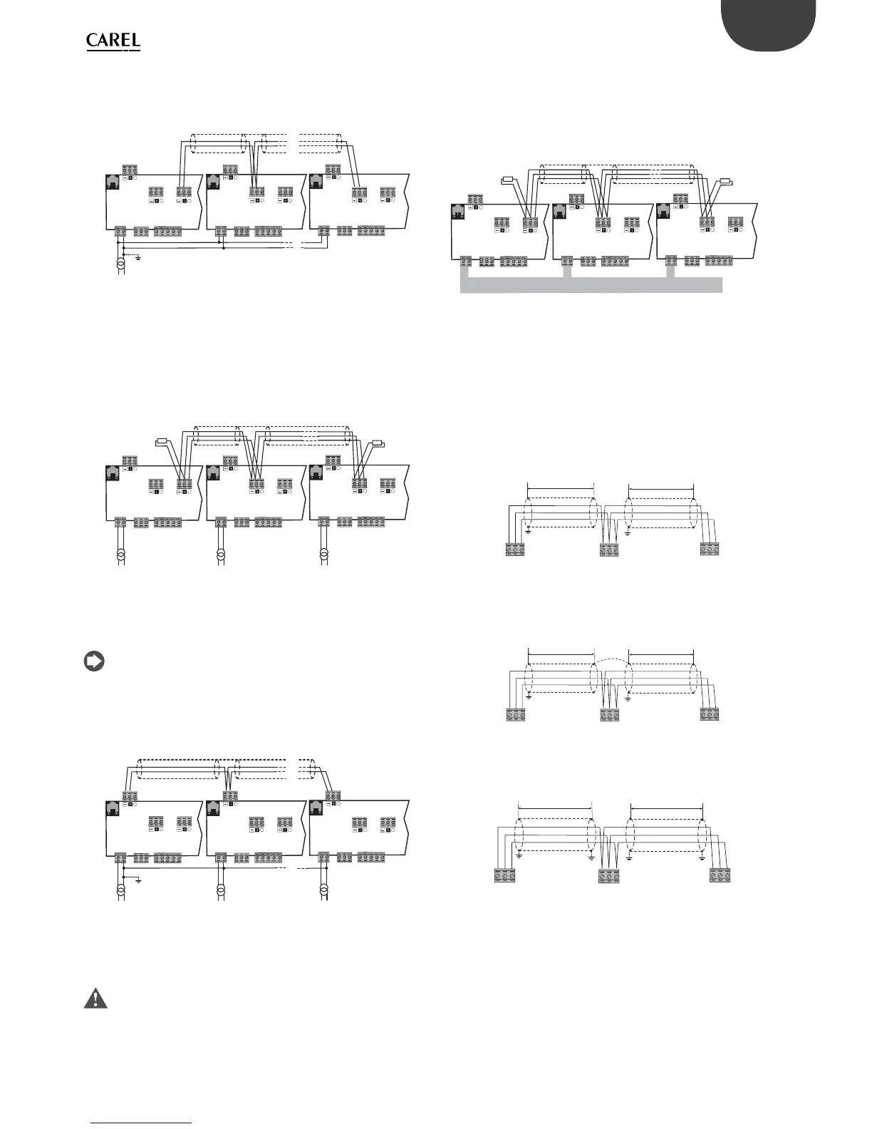
Optically-isolated serial port
This is the case of serial ONE - BMS1, serial TWO - Fieldbus 1 and the built-
in ports serials THREE and FOUR on optically-isolated models. Regardless
of the type of power supply or earthing, use a 3-pole shielded cable
connected as shown in the fi gure. If the network is more than 100 m
long, the terminating resistor is required.
J25 BMS2 J26 FBus2
J11 pLAN
pCO5+
G
G0
J25 BMS2
J26 FBus2
J11 pLAN
pCO5+
G
G0
J25 BMS2 J26 FBus2
J11 pLAN
pCO5+
G
G0
R = 120 Ω
R = 120 Ω
Power
supply
Fig. 4.f
The procedure for earthing the shield is described in the following
paragraph.
Procedure for earthing the shield
The shield of the serial cable is earthed diff erently according to the
length, as shown in the fi gure (where A=FBus terminal, B=BMS terminal,
or A=B in pLAN).
Case 1: Distance between controllers less than 0.3 m: earth only one end
of the cable.
L < 300 mm
L < 300 mm
AB B
Fig. 4.g
Case 2: Distance between controllers greater than 0.3 m: two possibilities.
a): Earth one end with a bridge between the shields.
L >300 mm
L > 300 mm
AB B
Fig. 4.h
b): Earth both ends of the cable.
L >300 mm
L > 300 mm
AB B
Fig. 4.i
Case 1: Multiple boards connected to a Master/Slave network powered
by the same transformer. This is a typical application of multiple boards
connected inside the same electrical panel. Terminating resistors are not
required (L<100m).
230 Vac
24 Vac
L
N
J25 BMS2 J26 FBus2
J11 pLAN
pCO5+
G
G0
J25 BMS2
J26 FBus2
J11 pLAN
pCO5+
G
G0
J25 BMS2 J26 FBus2
J11 pLAN
pCO5+
G
G0
Fig. 4.c
The procedure for earthing the shield is described in the following
paragraph.
Case 2: Multiple boards connected to a Master/Slave network powered
diff erent transformers (with G0 not earthed); this is a typical application
of multiple boards inside diff erent electrical panels. If the network is more
than 100 m long, the 120 Ω, ¼ W terminating resistor is required.
J25 BMS2 J26 FBus2
J11 pLAN
pCO5+
G
G0
J25 BMS2
J26 FBus2
J11 pLAN
pCO5+
G
G0
J25 BMS2 J26 FBus2
J11 pLAN
pCO5+
G
G0
230 Vac
24 Vac
L
N
230 Vac
24 Vac
L
N
230 Vac
24 Vac
L
N
R = 120 Ω
R = 120 Ω
Fig. 4.d
The procedure for earthing the shield is described in the following
paragraph.
Note: The diagrams for cases 1 and 2 also apply to pLAN networks
with the connection cable connected to terminals J11.
Case 3: Multiple boards connected to the pLAN network powered by
diff erent transformers with only one earth reference. This is a typical
application of multiple boards inside diff erent electrical panels.
J25 BMS2 J26 FBus2
J11 pLAN
pCO5+
G
G0
J25 BMS2
J26 FBus2
J11 pLAN
pCO5+
G
G0
J25 BMS2 J26 FBus2
J11 pLAN
pCO5+
G
G0
230 Vac
24 Vac
L
N
230 Vac
24 Vac
L
N
230 Vac
24 Vac
L
N
Fig. 4.e
The procedure for earthing the shield is described in the following
paragraph.
Important: The earth connection (if any) should be made only on
one point of the earth line (same earthing terminal for all controllers).