EasyManuals Logo

Carel pCO5+ User Manual

Carel pCO5+
60 pages
To Next Page IconTo Next Page
To Previous Page IconTo Previous Page
Page #25 background imageLoading...
Page #25 background image
25
ENG
pCO5plus +0300020EN rel. 1.2 - 07.11.2013
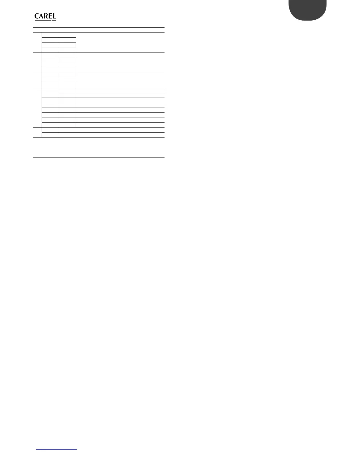
Only for pCO5+ built-in driver:
20
J27-1 1
Electronic expansion valve 1 control (see “Electro-
nic valve connection”).
J27-2 3
J27-3 2
J27-4 4
21
J28-1 1
Electronic expansion valve 2 control (see “Electro-
nic valve connection”).
J28-2 3
J28-3 2
J28-4 4
22
J30-1 VBAT
Power from external Ultracap module
J30-2 G0
J30-3 G
23
J29-1 GND Common for power supply to probes
J29-2 VREF Power to driver probes
J29-3 S1 Probe 1
J29-4 S2 Probe 2
J29-5 S3 Probe 3
J29-6 S4 Probe 4
J29-7 DI1 Digital input 1
J29-8 DI2 Digital input 2
24
A, B Valve A status LED
C, D Valve B status LED
Tab. 4.f
(*): Voltage A: 24 Vac or 28 to 36 Vdc;
(**): Voltage B: 230 Vac - 50/60 Hz.
: Large model; : Extralarge model.

Table of Contents

Questions and Answers:

Question and Answer IconNeed help?

Do you have a question about the Carel pCO5+ and is the answer not in the manual?

Carel pCO5+ Specifications

General IconGeneral
SeriespCO5+
Real-time ClockYes
Protection RatingIP20
ProcessorARM Cortex-M3
Communication PortsRS485
DisplayLCD with backlight
InputsDigital and Analog
OutputsRelay and Analog
Power Supply24 VAC/DC
Humidity10% to 90% non-condensing
ProtocolsModbus RTU, BACnet MS/TP
Input Voltage24 VAC/VDC
Weight300 g
Relay OutputsNumber varies depending on model
Analog OutputsNumber varies depending on model

Related product manuals