10
ENG
“SmartCella manual” +0300084EN - rel. 1.2 - 28.03.2017
4. Arm the circuit breakers and the motor protector
5. Close the front panel using the six screws
6. Power the panel on
7. Arm the main switch (yellow/red)
Warning
• separate the power cables (power supply, loads) from the signal cables
(probes, digital inputs) and the serial cable
• use cables that are suitably sized for the current they carry
• connect the terminal marked PE to the mains power supply earth
• after having powered the three-phase expansion, check correct
current draw of the various loads
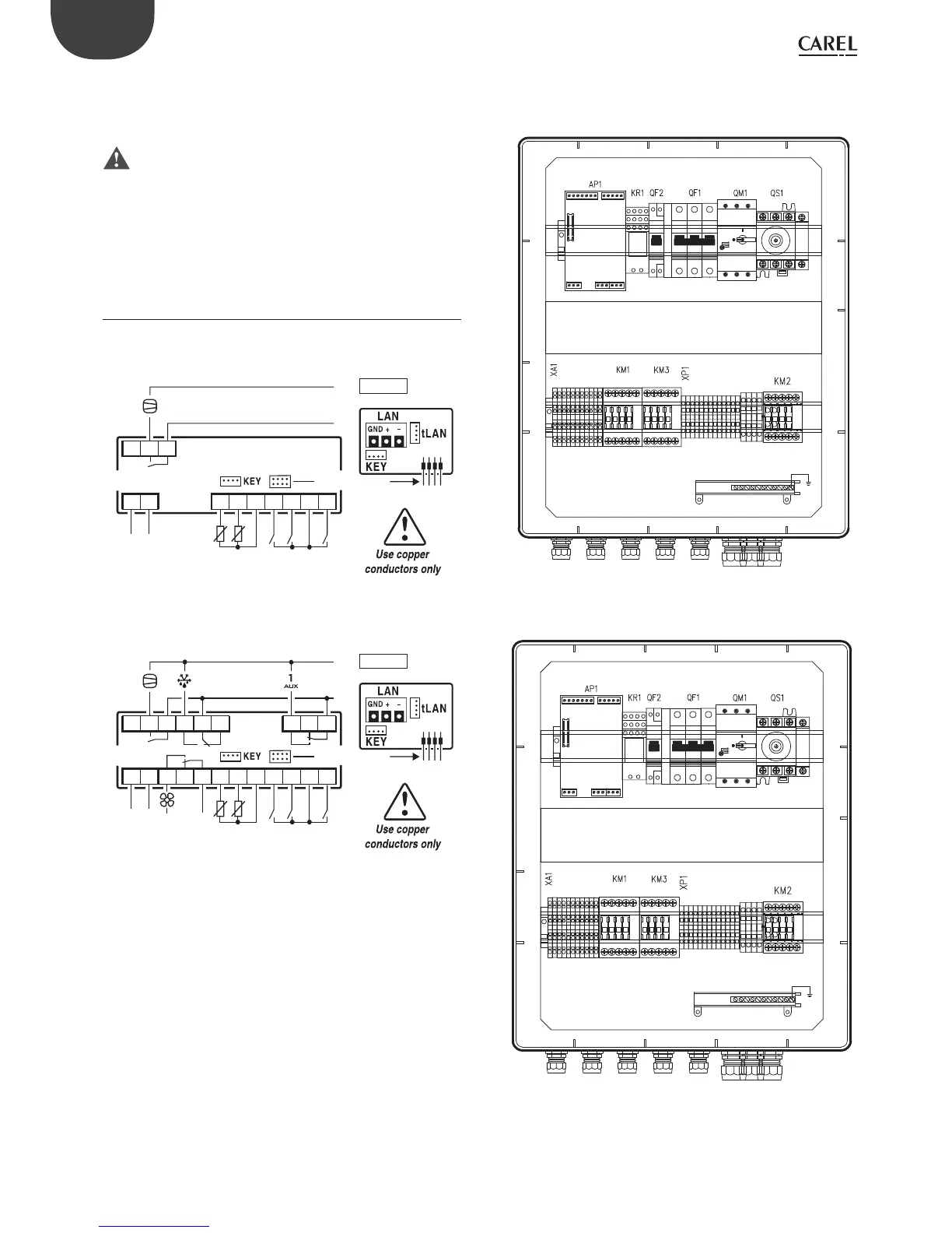
2.3 Wiring diagram
Single-phase version
WE00SxExxx
6 71 2
21 20 19
L
N
8 9 10 11 12
PROBES DIDI DI
12 2 3
1
R1
serial interface
230 V~
25mA~ max
POWER
SUPPLY
-10T45°C
IP 65
Fig. 2.d
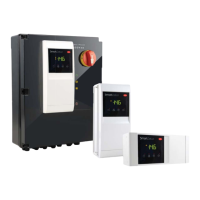
WE00CxHxxx
5
R4
6 7
LN
1 2
24 23 22 21 20 19 15 14 13
L
N
8 9 10 11 12
PROBES DIDI DI
12 2 3
1
R1 R2 R3
serial interface
3 4
115…230 V~
50mA~ max
POWER
SUPPLY
-10T50°C
IP 65
Fig. 2.e
Three-phase version
Layouts and components
(WP00B34A10, WP00B24A10, WP00B14A10)
Fig. 2.f
WP00B57B20, WP00B47B20, WP00B44A10
Fig. 2.g