20
ENG
“SmartCella manual” +0300084EN - rel. 1.2 - 28.03.2017
Functions that can be disabled on the keypad
Important: if setting H2 ≠ 1, 3, the type F parameters cannot be set,
but rather only their values can be displayed. Type C parameters, being
password-protected, can always be set on the keypad following the
procedure described in chap. 3. If “set point” and “F parameter” setting is
disabled, the set point and the type F parameters cannot be set, but
rather only their values can be displayed.
Note: Y = can be activated / enabled; N = cannot be activated /
enabled
par. H2
FUNCTION 0123456
LIGHT Y Y Y Y Y Y Y
AUX YYYYYYY
ON/OFF Y Y Y Y N N Y
HACCP YYYYYYY
PRG/MUTE (mute) Y Y Y Y Y Y Y
UP+DOWN (continuous cycle) Y Y Y Y N N N
SET/DEF (defrost) Y Y Y Y N N N
SET (set point) setting N Y N Y Y N N
“F” parameter setting N Y N Y N N N
Tab. 4.h
Disable buttons
Using the individual bits, the functions relating to the buttons on the
keypad can be enabled or disabled, according to the relationships shown
in the table below: to calculate the value to be assigned to parameter H6,
simply sum the values assigned to the functions that should be disabled.
Note: the functions disabled using parameter H6 are added to
those disabled using parameter H2.
Disable buttons
Bit Value par. H6 Button Function
01 Display defrost temp.; enter HACCP; defrost
12
Activation of
AUX output 1, continuous cycle
24 Up, On-Off
38 Mute alarms
Tab. 4.i
4.2 Loading the sets of parameters
Up to 6 sets of custom parameters can be selected on the controller, after
having been loaded using the VPM programming tool (Visual Parameter
Manager, see appendix 1) and the programming key.
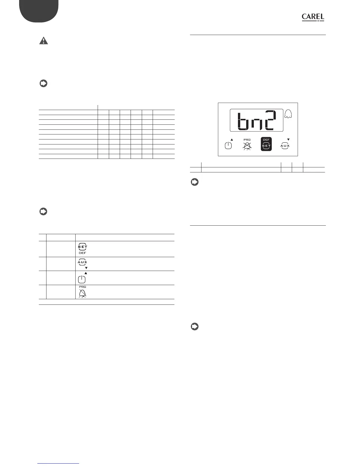
Procedure:
• power down the controller;
• power up while holding Prg/mute;
• the display will show the fi rst set: bn0;
• press UP/DOWN to select set bn1 to bn6. For example, select bn2;
• press Set to confi rm the selected set: the controller will load the set
of parameters called bn2 and then will return to the standard display.
Par. Description Def Min Max UOM
Hdn Number of default parameter sets available 0 0 6 -
Tab. 4.j
Note: bn0 is the default set of parameters on the controller, i.e. the
default confi guration. When one of sets bn1 to bn6 is loaded, bn0 is
overwritten with the new set and is consequently erased.
4.3 Preparing for operation
Once having completed the installation, confi guration and programming
procedures, before starting the controller, check that:
• the wiring has been completed correctly;
• the programming logic is suitable for controlling the unit and the
system being managed;
• if the controller is fi tted with RTC (clock), set the current time and date,
and the on and off times for the light/auxiliary output;
• set the standard display;
• set the “probe type” parameter based on the probe available and the
type of control (NTC, NTC-HT, PTC); note that the controllers that use
PTC probes may have diff erent part numbers from those that only use
NTC probes;
• set the type of defrost: heater or hot gas;
• set the temperature unit of measure (°C or °F);
• the protection functions (delay at start-up, rotation, minimum on and
off times for the outputs) are active.
Note: all the alarms with manual reset can be reset by pressing the
Prg and UP buttons together for more than 5 seconds. See the chapter on
“Alarms”.