26
ENG
“SmartCella manual” +0300084EN - rel. 1.2 - 28.03.2017
6. CONTROL
6.1 Switching the controller On/O
The controller can be switched ON/OFF from a number of sources;
keypad, supervisor and digital input. In this operating mode, the display
will be show the temperature selected for parameter /tI, alternating with
“OFF”. The digital input can be used to switch the controller on/off , setting
parameter A4/A5 to “6”. Switching on/off from digital input has priority
over the same function from the supervisor and the keypad.
Source Priority Note
Digital input 1 Disable On/Off from keypad and supervisor
Keypad 2
Supervisor 3
Tab. 6.a
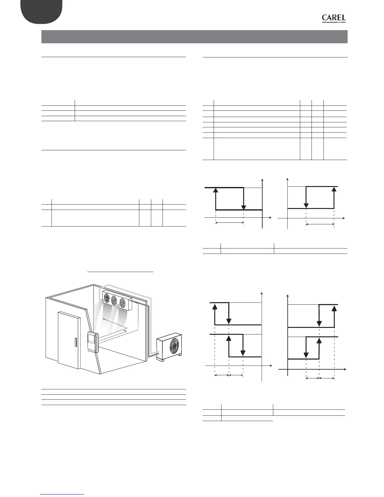
6.2 Virtual probe
The control output is the compressor output, which in most cases is also
associated with the evaporator fan output. The control probe is probe S1,
while probes S2, S3, S4 and S5 can be assigned functions such as product
probe (display only), defrost probe, condenser probe or frost protection
probe. In special cases, it is useful to defi ne the virtual probe (Sv) as the
control probe, being ideally the average between the outlet probe and
the intake probe.
Par. Description Def Min Max UOM
St Set point 0 r1 r2 °C/°F
/4 Virtual probe composition
0 = control probe S1
100 = probe S2
0 0 100 -
Tab. 6.b
Parameter /4 is used to determine the virtual probe (Sv) as the weighted
average of control probe S1 and probe S2, according to the following
formula:
Sv =
[ S1*(100 - /4) + S2*/4
100
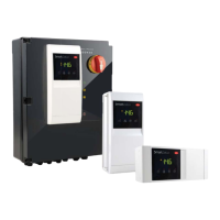
SmartCella
Fig. 6.a
Key
S1 Outlet probe
Sv Virtual probe
S2 Intake probe
6.3 Set point
The reference output is the compressor output (CMP).
The controller can operate in 3 diff erent modes, as selected by parameter
r3:
• direct with defrost control;
• direct;
• reverse.
Par. Description Def Min Max UOM
St Set point 0 r1 r2 °C/°F
rd Diff erential 2.0 0.1 20 °C/°F
rn Neutral zone 4.0 0.0 60 °C/°F
rr Reverse diff erential 2.0 0.1 20 °C/°F
r1 Minimum set point -50 -50 r2 °C/°F
r2 Maximum set point 60 r1 200 °C/°F
r3 Operating mode
0 = Direct with defrost control (cooling)
1 = Direct (cooling)
2 = Reverse (heating)
002-
Tab. 6.c
ON
OFF
Sv
CMP
REVERSE
St
rd
ON
OFF
Sv
CMP
St
rd
DIRECT
Fig. 6.b
Key
St Set point rd Diff erential
Sv Virtual probe CMP Compressor
If the second compressor output is activated (H1 = 12) on the AUX output,
the compressor output is activated at St±rd/2 and the AUX output at
St±rd, as illustrated in the following fi gure.
ON
OFF
CMP
ON
OFF
Sv
rd/2
AUX
rd/2
REVERSE
St
ON
OFF
St
Sv
rd/2
CMP
ON
OFF
rd/2
AUX
DIRECT
Fig. 6.c
Key
St Set point rd Diff erential
Sv Virtual probe AUX Auxiliary output
CMP Compressor
The neutral zone is activated on the controller only if the reverse output
is activated with neutral zone control, H1 = 11.