53
ENG
“SmartCella manual” +0300084EN - rel. 1.2 - 28.03.2017
11.9 Defrost with 2 evaporators
Up to 3 defrost probes and up to 2 evaporator outputs can be confi gured.
The controller recognises the basic confi guration shown in the table
below (probe 1 is the control probe and cannot be confi gured).
DEFROST PROBE AND EVAPORATOR OUTPUT CONFIGURATION
Case Defrost probes Evaporator
outputs
Notes
1 Probe 2 Evap. 1 Probe 2 acts on evap. 1
2 Probe 2 Evap. 1
and 2
Probe 2 acts on evap. 1 and 2
3 Probe 2 Evap. 1 Probes 2 and 3 act on evap. 1 (start
and end defrost refer to the probe
with the lower value)
Probe 3
4 Probe 2 Evap. 1 Probes 2, 3, 4 act on evap. 1 (start and
end defrost refer to the probe with the
lower value)
Probe 3
Probe 4
5 Probe 2 Evap. 1 Probe 1 acts on evap. 1
Probe 3 Evap. 2 Probe 2 acts on evap. 2
6 Probe 2Probe 4 Evap. 1 Probe 2 and 4 act on evap. 1 (end
defrost if all probes > end defrost
threshold.)
Probe 3Probe 4 Evap. 2 Probe 3 and 4 act on evap. 2 (end
defrost if all probes > end defrost
threshold.)
Tab. 11.c
Case 6 refers to the confi guration with 1 probe on each evaporator and
1 probe in common.
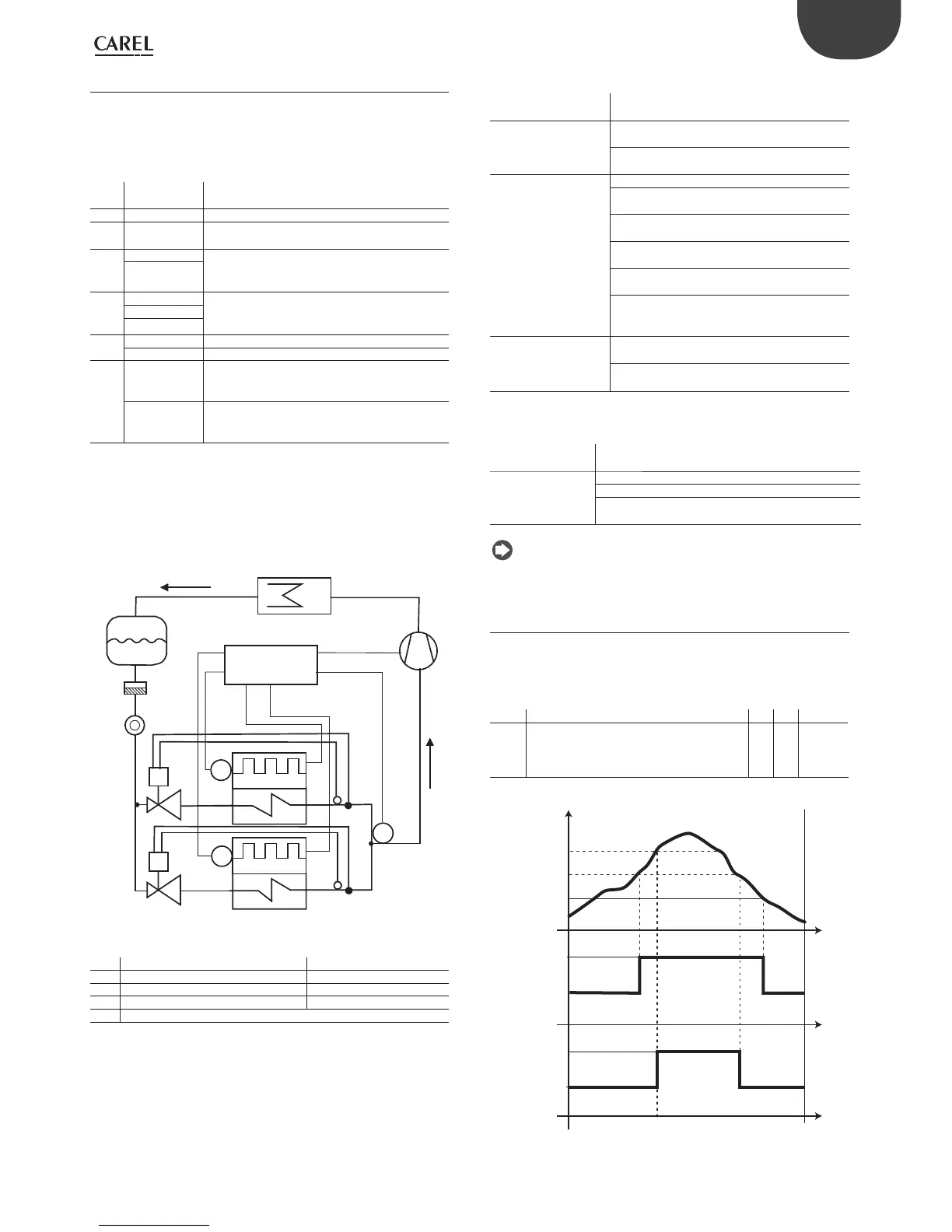
CASE 6: probe 2, probe 4 on evaporator 1, probe 3, probe 4 on
evaporator 2.
C
L
CMP
T
V1
T
V2
E2
E1
S2
S3
S4
Smar tCella
S
F
Fig. 11.a
Key
E1/2 Evaporator 1/2 S2/3/4 Defrost probe 2, 3, 4
C Condenser CMP Compressor
V1/2 Electronic expansion valve 1/2 F Filter-drier
L Liquid receiver S Liquid gauge
V1/2 Thermostatic expansion valve 1/2
The following situations may occur if the outputs are not confi gured or
there are probe alarms.
DEFROST BY TEMPERATURE
Defrost probe / evap.
output confi g.
Situation Eff ect
Probe 2 defrost output 1 No probe Defrost ends by timeout
(dP1)
Probe available, probe
error
Defrost ends by timeout
(dP1)
Probe 3
defrost output 2
No probe
AUX1 confi gured Defrost ends by timeout
(dP1)
AUX2 confi gured Defrost ends by timeout
(dP2)
AUX1 and AUX2 not
confi gured
Not performed
Probe available, probe
error
Defrost ends by timeout
(dP2)
Probe available and
AUX1 and AUX2 not
confi gured
Defrost performed on
defrost output
Probe 4 together with
probe 2 and probe
3defrost output 1 and
defrost output 2
No probe, not managed Cases 4, 6 not
recognised
Probe available, probe
error
Defrost ends by timeout
Tab. 11.d
DEFROST BY TIME
Defrost probe /
evap. output con g.
Situation E ect
Defrost output 1 AUX1 confi gured Defrost ends by timeout (dP1)
AUX2 confi gured Defrost ends by timeout (dP2)
AUX1 and AUX2
not confi gured
Defrost not performed
Tab. 11.e
Note: AUX1 and AUX 2 confi gured as evaporator outputs are not
equivalent..
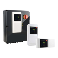
11.10 Second compressor with rotation
Second compressor output with two step control and rotation. The
role of main and secondary compressor are alternated whenever the
compressor stops, so that when next called to start (or stop), the output
not involved in the previous start (stop) will be activated (deactivated).
Par. Description Def Min Max UoM
H1/H5 AUX/AUX2 output confi guration
0 = normally energised alarm
…
13 = second compressor step with rotation
1/3 0 13 -
Tab. 11.f
ON
OFF
CP1
CP2
Sv
ON
OFF
St
St+rd
St+rd/2
t
t
t
Fig. 11.b