13
ENG
“SmartCella manual” +0300084EN - rel. 1.2 - 28.03.2017
2.4 Installation
To install the controller, proceed as follows, with reference to the wiring
diagrams shown in the previous paragraphs:
1. connect the probes and power supply: the probes can be installed up
to a maximum distance of 10 m from the controller, using shielded
cables with a minimum cross-section of 1 mm². To improve immunity
to disturbance, use probes with shielded cables (connect only one end
of the shield to the earth on the electrical panel);
2. program the controller: as shown in the chapters “Commissioning” and
“User interface”;
3. connect the actuators: the actuators should only be connected after
having programmed the controller. Carefully check the maximum
capacities of the relays or three-phase contactors, as indicated in the
“technical specifi cations”;
4. serial network connection: all controllers are fi tted with a serial
connector for connection to the supervisor network via the serial
interface (IROPZ485*0 or serial board IROPZSER30). The secondary
of the transformers that supply the controllers must not be earthed.
If connection to a transformer with earthed secondary winding is
required, an insulating transformer must be installed in between.
Important: a separate transformer must be used for each controller,
- NEVER connect multiple controllers to the same transformer.
Warnings: avoid installing the controller in environments with the
following characteristics:
• relative humidity greater than 90% non-condensing;
• strong vibrations or knocks;
• exposure to continuous water sprays;
• exposure to aggressive and polluting atmospheric agents (e.g.: sulphur
and ammonia gases, saline mist, smoke) which may cause corrosion
and/or oxidation;
• strong magnetic and/or radio frequency interference (for example ,
near transmitting antennae);
• exposure to direct sunlight and the elements in general.
The following warnings must be observed when connecting the
controllers:
• incorrect connection of the power supply may seriously damage the
controller;
• use cable ends suitable for the corresponding terminals. Loosen each
screw and insert the cable ends, then tighten the screws and gently
pull the cables to check their tightness. When tightening the screws,
do not use automatic screwdrivers, rather adjust tool tightening
torque to less than 0.5Nm;
• separate as much as possible (by at least 3 cm) the probe signal and
digital input cables from inductive loads and power cables, to avoid
any electromagnetic disturbance. Never lay power cables and probe
cables in the same cable conduits (including those for the electrical
panels). Do not install the probe cables in the immediate vicinity of
power devices (contactors, circuit breakers or the like). Reduce the
length of the sensor cables as much as possible, and avoid spirals
around power devices;
• only use IP67 guaranteed probes as end defrost probes; place the
probes with the vertical bulb upwards, so as to facilitate drainage
of any condensate. Remember that thermistor temperature probes
(NTC) have no polarity, so the order the ends are connected in is not
important.
Cleaning the controller
When cleaning the controller do not use ethanol, hydrocarbons (petrol),
ammonia and by-products. Use neutral detergents and water.
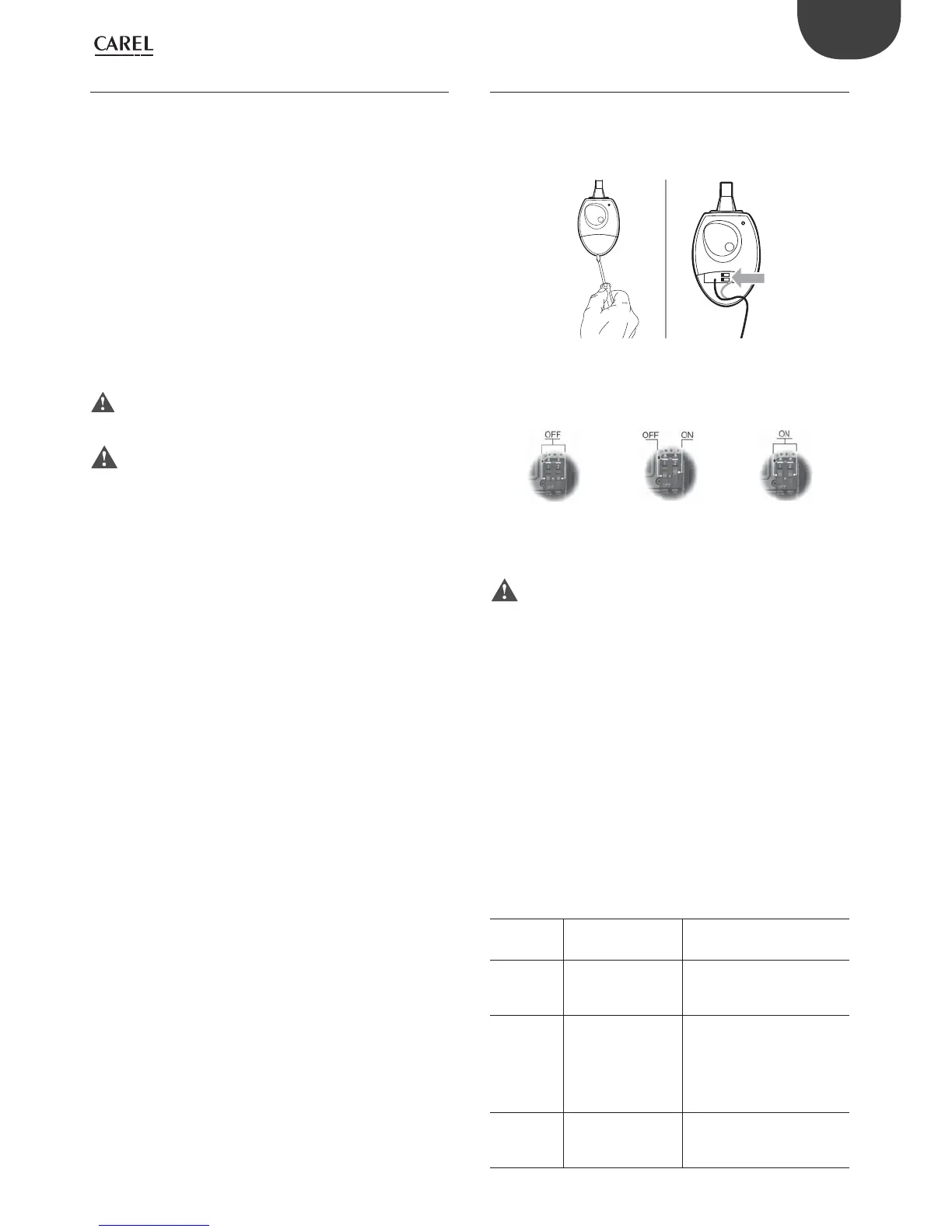
2.5 Programming key IROPZKEY00/A0
The programming key can load up to 7 diff erent parameter confi gurations
onto the controller (the controller operating parameters plus 6 sets
of customisable default parameters). The keys are plugged into the
connector (4 pin AMP) available on the controllers. All the operations can
be performed with the controller off .
Fig. 2.j
The functions are selected by setting the two dipswitches, accessible by
removing the battery cover.
UPLOAD DOWNLOAD EXTENDED DOWNLOAD
• load the parameters from a controller onto the key (UPLOAD);
• copy from the key to a controller (DOWNLOAD);
• extended copy from the key to a controller (EXTENDED DOWNLOAD).
Important: The parameters can only be copied between
controllers with the same part number. The UPLOAD operation can,
however, always be performed.
Copying and downloading the parameters
The following operations are used for the UPLOAD and/or DOWNLOAD
functions, simply by changing the settings of the dipswitches on the key:
1. open the rear cover on the key and position the 2 dipswitches according
to the desired operation;
2. close the rear cover on the key and plug the key into the connector on
the controller;
3. press the button and check the LED: red for a few seconds, then green,
indicates that the operation was completed correctly. Other signals
or the fl ashing of the LED indicates that problems have occurred: see
the table below;
4. at the end of the operation, release the button, after a few seconds the
LED goes off ;
5. remove the key from the controller.
LED signal Error Meaning and solution
Red LED
fl ashing
Batteries discharged at
start copy
The batteries are discharged,
the copy operation cannot be
performed. Replace the batteries.
Green LED
fl ashing
Batteries discharged
during copy or at end
of copy
During the copy operation or
at the end of the operation the
battery level is low. Replace the
batteries and repeat the operation.
Red/green
LEDs fl ashing
(orange signal)
Controller not
compatible
The parameter set-up cannot be
copied as the connected controller
model is not compatible. This error
only occurs for the DOWNLOAD
function; check the controller
P/N and run the copy only for
compatible models.
Red and green
LEDs on
Error in data being
copied
Error in the data being copied.
The EEPROM on the controller
is corrupted, therefore the data
cannot be copied to/from the key.