21
ENG
“SmartCella manual” +0300084EN - rel. 1.2 - 28.03.2017
5. FUNCTIONS
5.1 Probes (analogue inputs)
The SmartCella platform controllers feature a maximum of 5 analogue
inputs, which are used for NTC, high temperature NTC (NTC Enhanced
Range) or PTC temperature sensors (see the note below). Probes S3, S4
and S5 can also be confi gured as digital inputs. Probe S1 is the control
probe and its function cannot be changed; the functions of probes S2, S3,
S4, S5 can be selected using parameters /A2, /A3, /A4, /A5. The probes can
be calibrated to adjust their readings. In particular, parameters /c1 to /c5
are used to increase or decrease the values read by the probes connected
to inputs S1, S2, S3, S4, S5 across the entire the range of measurement. For
the calibration procedure, see paragraph 3.5.
Par. Description Def Min Max UOM
/P Type of probe
0 = NTC Standard Range -50T90°C
1 = NTC Enhanced Range -40T150°C
2 = PTC Standard Range -50T150°C
002-
/c1 Probe 1 calibration 0 -20 20 °C/°F
/c2 Probe 2 calibration 0 -20 20 °C/°F
/c3 Probe 3 calibration 0 -20 20 °C/°F
/c4 Probe 4 calibration 0 -20 20 °C/°F
/c5 Probe 5 calibration 0.0 -20 20 °C/°F
Tab. 5.a
A
T1
T2
min max
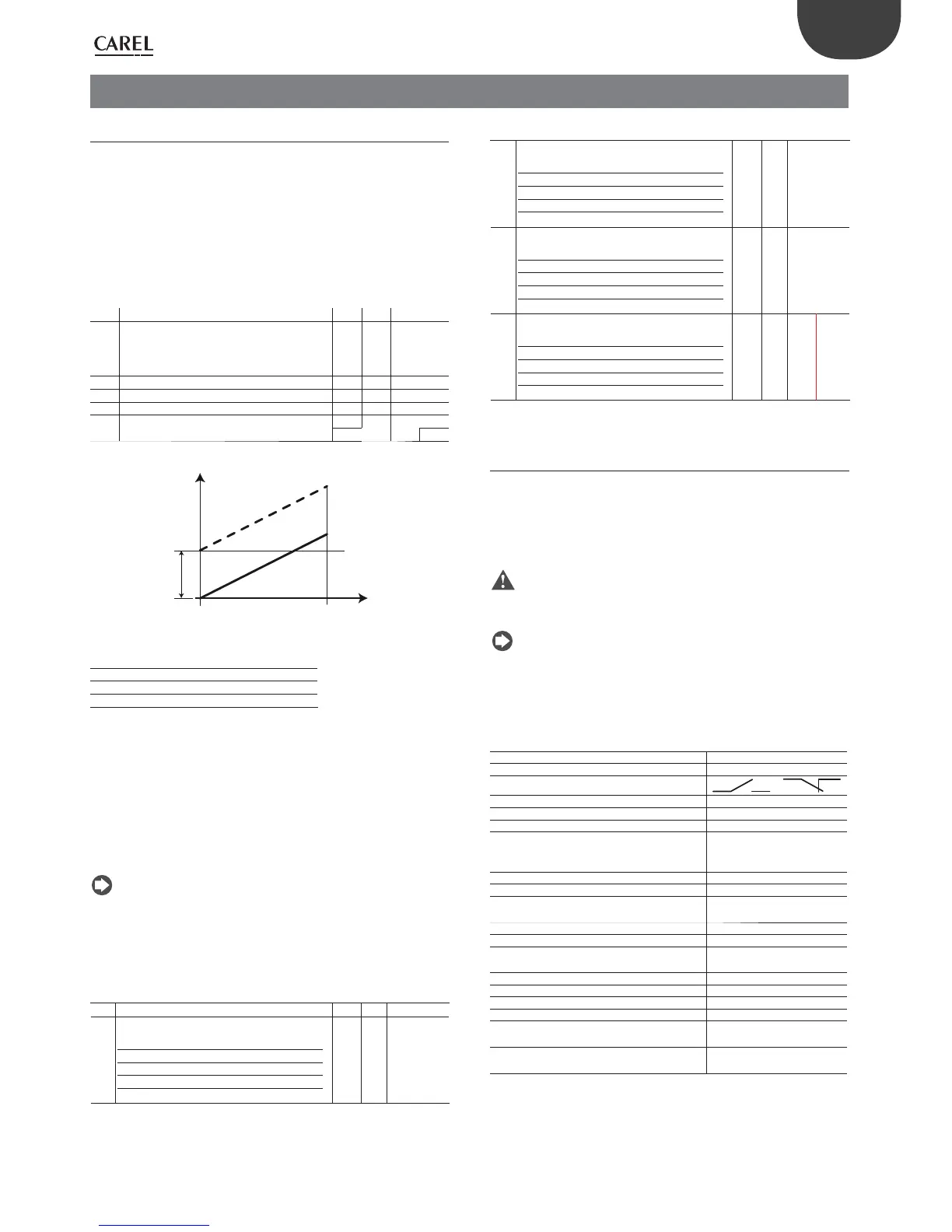
Fig. 5.a
Key
T1 Temperature read by the probe
T2 Value calibrated by T1
A Calibration value
min, max Range of measurement
Assigning the functions of probes S2, S3, S4, S5
The controller, inside the cold room, can use the following probes:
• defrost, located on the evaporator, preferably where ice remains the
longest;
• condenser, used to protect the compressor against high pressure
when the condenser is off or the condenser fan is malfunctioning;
• frost protection, to activate the corresponding alarm.
Note:
• to confi gure probes 3, 4 and 5 as digital input 1, 2 and 3 respectively,
set parameters /A3 e /A4 and /A5 =0;
• if multiple probes have been confi gured with the same operating
mode, the controller will use the fi rst probe in increasing order with
that confi guration.
Par. Description Def Min Max UOM
/A2 Probe 2 confi guration (S2) (M models) 0 0 4 -
/A2 Probe 2 confi guration (S2)
0 Absent
1 Product (display only)
2 Defrost
3 Condenser
4 Frost
204-
Par. Description Def Min Max UOM
/A3 Probe 3 confi guration (S3)
0 Digital input 1 (DI1)
1 Product (display only)
2 Defrost
3 Condenser
4 Frost
003-
/A4 Probe 4 confi guration (S4/ DI2)
0 Digital input 2 (DI2)
1 Product (display only)
2 Defrost
3 Condenser
4 Frost
004-
/A5 Probe 5 calibration (S5/ DI3)
0 Digital input 3 (DI3)
1 Product (display only)
2 Defrost
3 Condenser
4 Frost
004-
Tab. 5.b
5.2 Digital inputs
Digital inputs DI1, DI2 and DI3 respectively can be enabled in the place
of probes S3, S4 and S5. Digital inputs 1, 2, 3 must fi rst be enabled (par. /
A3 and /A4 = 0) and then assigned to a specifi c function (par. A4, A5 and
A9). Finally, an external contact can be connected to the multifunction
input to activate various types of functions, such as alarms, curtain/door
switches, start defrost, etc. See the table below.
Important: to ensure unit safety in the event of serious alarms, the
unit must be fi tted with all the electromechanical safety devices needed
to guarantee correct operation..
Note: (applies to all settings of par. A4, A5 and A9): if 2 digital inputs
are confi gured in the same way, for example to enable defrost, the disable
event is generated when at least one of the inputs is open, while the
enable event is generated when at both inputs are closed.
Digital input functions
PARAMETERS A4, A5 and A9
Setting Contact
OPEN CLOSED
0 = not active - -
1 = immediate external alarm active not active
2 = delayed external alarm active not active
3 = select probe see /tI fi rst probe
enabled (/A2,
/A3, /A4, /A5)
3 = enable defrost (all other models) not enabled enabled
4 = start defrost not active active
5 = door switch with compressor and
evaporator fans off
door open door closed
6 = remote ON/OFF OFF ON
7 = curtain switch curtain open curtain closed
8 = low pressure switch low pressure
status
normal status
9 = door switch with fans off door open door closed
10 = direct/reverse operation direct mode reverse mode
11 = light sensor light off light on
12 = activate aux output deactivated activated
13 = door switch with compressor and fans
off and light not managed
door open door closed
14 = door switch with fans off and light not
managed
door open door closed
Tab. 5.c