14
ENG
“SmartCella manual” +0300084EN - rel. 1.2 - 28.03.2017
Red LED on
steady
Data transfer error The copy operation was not
completed due to a serious error
when transferring or copying the
data. Repeat the operation, if the
problem persists check the key
connections.
LEDs off Batteries disconnected Check the batteries.
Tab. 2.g
Note: the DOWNLOAD operation (normal or extended) is possible
even if the operating and control parameters are incorrect; in this case,
they will be recovered from the key. Be careful when recovering the unit
parameters from a key, as these determine the low-level operation of the
controller (unit model, type of interface, assignment of logical relay to
physical relay, brightness of the display, level of modulation of the relay
control signal …). The unit parameters from the original model must
therefore be restored to ensure correct operation of the controller.
2.6 Remote display connection
To connect the remote display, use the dedicated cable (P/N PSTCON0*B0)
and serial card (P/N IROPZSER30). See the following diagram.
Also set a value >0 for parameter /tE, to display the reading on the remote
display.
Par. Description Def Min Max UOM
/tE Reading on remote display 0 6 6 -
0 Not fi tted 4 Probe 3
1 Virtual probe 5 Probe 4
2 Probe 1 6 Reserved
3 Probe 2
Tab. 2.a
2.7 Network connection
Warnings:
• As serial converter, both IROPZSER30 and IROPZ485x0 can be used;
• the RS485 converter is sensitive to electrostatic discharges and
therefore must be handled with extreme care;
• check the documents on the serial interface for connection instructions,
so as to avoid damaging the controller;
• fasten the converter properly so as to prevent disconnection;
• complete the wiring without power connected;
• keep the serial interface cables separate from the power cables (relay
outputs and power supply).
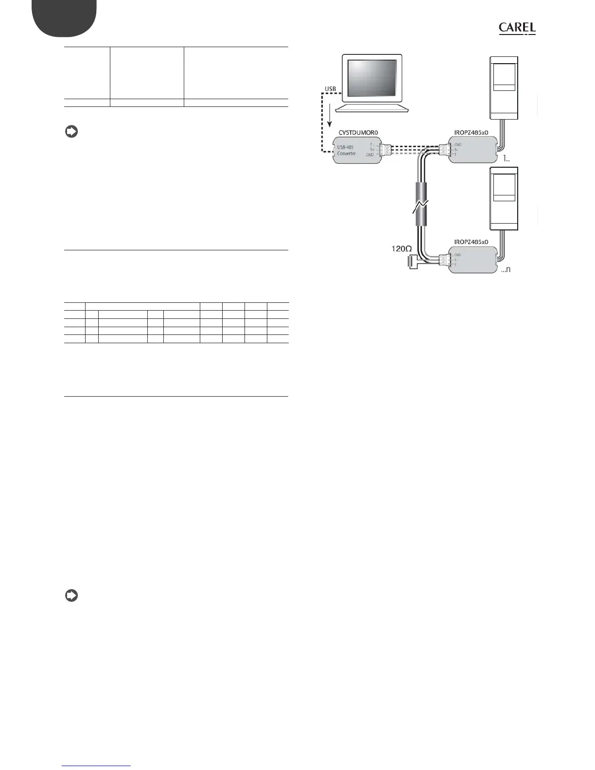
The RS485 converter is used to connect SmartCella to the supervisor
network for the complete management and monitoring of the connected
controllers. The system allows a maximum of 207 units, with a maximum
length of 1000 m. Connection requires the standard accessories (RS485-
USB converter, CAREL P/N CVSTDUMOR0) and a 120 Ω terminating resistor
to be installed on the terminals of the last connected controller. Connect
the RS485 converter to the controllers and make the connections as
shown in the fi gure. To assign the serial address, see parameter H0. See
the instruction sheets on the converters for further information.
Note: SmartCella can communicate with both Carel and Modbus
protocols with auto-recognition
SmartCella
SmartCella
Fig. 2.k