42
ENG
“SmartCella manual” +0300084EN - rel. 1.2 - 28.03.2017
9. TECHNICAL SPECIFICATIONS
9.1 Technical speci cations
Single-phase version
Power supply
Model Voltage Power
E 230 V~ (+10%, -15%), 50/60 Hz 3 VA, 25 mA~ max.
A 115 V~, (+10%, -15%) 50/60 Hz 3 VA, 50 mA~ max.
H 115...230 V~ (+10%, -15%), 50/60 Hz 6 VA, 50 mA~ max.
L 12...24 V~ (+10%, -15%), 50/60 Hz, 12...30 Vdc 3 VA, 300 mA~ /mAdc max.
0 12 V~, 50/60 Hz, 12...18 Vdc Only use TRA12VDE00 fuse transformer in the late 315 mA delayed
Insulation guaranteed by
the power supply
E, A, H
insulation from extra low voltage parts reinforced, 6 mm clearance, 8 mm creepage, 3750V insulation
insulation from relay outputs basic, 3 mm clearance, 4 mm creepage, 1250V insulation
0, L
insulation from extra low voltage parts to be guaranteed externally by safety transformer (SELV)
insulation from relay outputs reinforced, 6 mm clearance, 8 mm creepage, 3750 V insulation
Inputs S1 (probe 1) NTC
S2 (probe 2) NTC
DI1 S3 (probe 3) voltage-free contact, contact resistance < 10 , closing current 6 mA/ NTC
DI2 S4 (probe 4) voltage-free contact, contact resistance < 10 , closing current 6 mA/ NTC
Maximum distance between probes and digital inputs less than 10 m. Note: in the installation it is recommended to separate the
power and load connections from the probe, digital input, display and supervisor cables.
Probe type
Std. Carel NTC
10 kΩ a 25 °C, range –50T90 °C
measurement
error:
1 °C in the range -50T50 °C
3 °C in the range 50T90 °C
High temperature NTC
50 kΩ a 25 °C, range -40T150 °C
measurement
error:
1,5 °C in the range -20T115 °C
4 °C in the range outside of -20T115 °C
Relay
outputs
depending on the model
EN60730-1 UL873
relè 250 V~ operating cycles 250 V~ cicli manovra
8 A(*) 8(4)A on N.O.
6(4)A on N.C.
2(2)A on N.O. and N.C.
100000 8 A res. 2 FLA 12 LRA C300 30000
16 (*) 10(4) A to 60 °C on N.O.
12(2)A on N.O. and N.C.
100000 12 A res. 5 FLA 30 LRA C300 30000
2 Hp 10(10)A 100000 12 A res. 12 FLA 72 LRA C300 30000
(*): Relay not suitable for fl uorescent loads (neon lights, etc.) that use starters (ballasts) with phase shifting capacitors. Fluorescent lamps with
electronic controllers or without phase shifting capacitors can be used, depending on the operating limits specifi ed for each type of relay.
insulation from extra low voltage parts reinforced, 6 mm clearance, 8 mm creepage, 3750 V insulation
insulation between independent relay outputs basic, 3 mm clearance, 4 mm creepage, 1250 V insulation
Connections Cable cross-section from 0.5 to 2.5 mm
2
max current 12 A
connection type section Maximum current
fi xed screw connectors
removable connectors for screw blocks
0,5 - 2,5 mq 12 A
conductor section for probes/digital inputs 0,5 - 2,5 mq da 20 a 13 AWG
conductor section for power supplys/loads 0,5 - 2,5 mq da 15 a 13 AWG
The correct sizing of the power and connection cables between the instrument and the loads is the installer’s responsibility. Depending
on the model, the maximum current at common terminals 1, 3 or 5 is 12 A. If using the controller at maximum operating temperature
and at full load, the cables used must be suitable for operation at least up to 105 °C.
Case plastic dimensions 128x290x101 mm
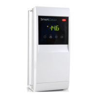
Display digit 3 digit LED
display da -99 a 999
functioning mode showned with graphic icons on display
Keypad 4 buttons keppad membrane
Buzzer available on all models
Operating temperature models 0,L,H -10T50 °C
models E,A -10T45°C
Operating humidity <90% U.R. no condensing
Storage temperature -20T70 °C
Storage humidity <90% U.R. no condensing
Front panel degree of protection IP65 on the frontal
Control pollution status 2 (in normal)
PTI of insulating materials plastic molds 250 plastic and insulating materials 175
Period of stress across the insulating parts long
Heat and re resistance category category D e category B (UL 94-V0)
Class of protection against voltage surge category II
Type of action and disconnection 1.B relay contact (micro-switching)
Construction of control Built-in, electronic
Classi cation according to protection against electric shock Class II, by suitable incorporation
Device to be hand-held or incorporated into equipment intended to be
manually held
no
Software class and structure classe A
Frontal Cleaning of the controller Use only neutral detergents and water.
Serial interface CARELnetwork extern. Available on all models, upon request
Interface for per display repeater extern. Available on models H, L, 0 upon request
Maximum distance between interface and display 10 m
Programming key available on alls models
Safety standards: compliant with relevant European standards
Tab. 9.a