28
ENG
“SmartCella manual” +0300084EN - rel. 1.2 - 28.03.2017
ON
OFF
ON
OFF
t
CMP,
FAN
VPD
c7
PRESSURE
SWITCH
St
ON
OFF
AtS
ON
OFF
Sv
c7
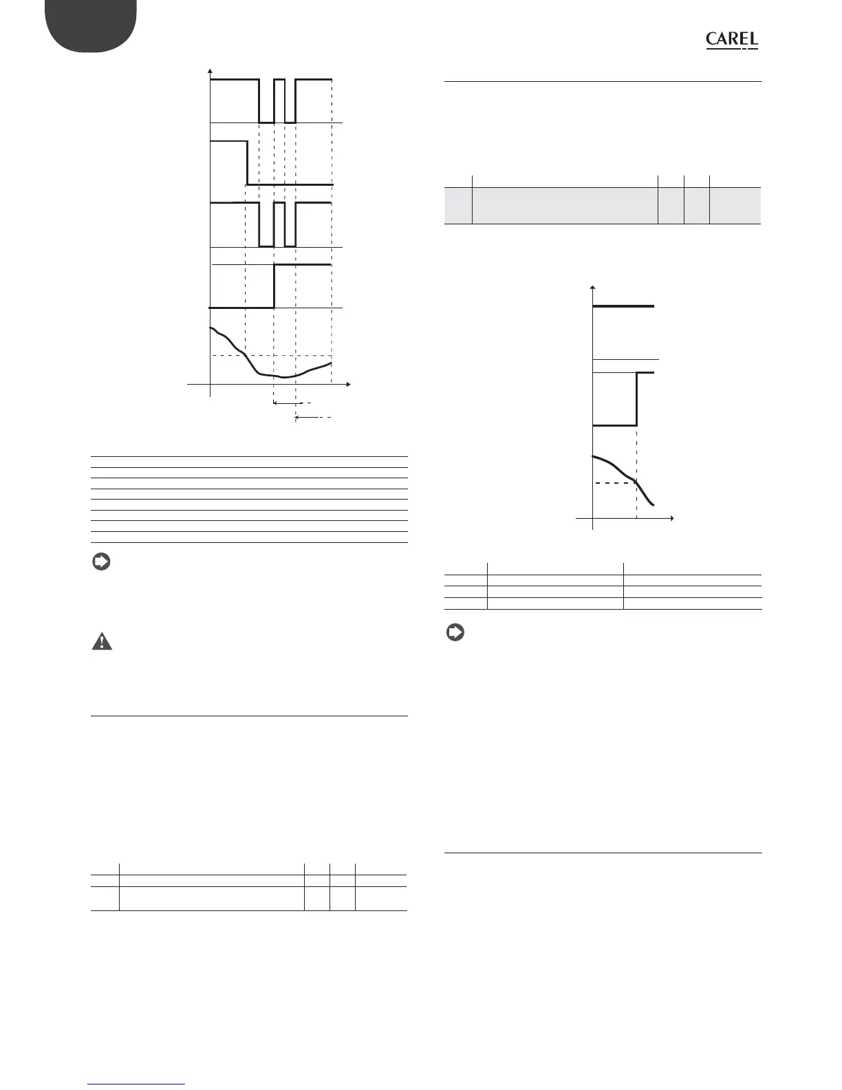
Fig. 6.h
Key
CMP, FAN Compressor, fan
VPD Pump down valve
Pressure switch Pressure switch
Sv Control probe
St Set point
c7 Maximum pump down time
t Time
AtS Autostart in pump down
Note:
• in the compressor autostart function, the protection times c1 and c2
are applied, but not c3;
• The message “AtS” is reset automatically when the next pump down
cycle terminates correctly.
Important: in the event of “Pd” alarms, the autostart function is
deactivated.
6.6 Continuous cycle
For information on activating the continuous cycle from the keypad, see
chapter 3. The value of parameter cc must be >0. During operation in
continuous cycle, the compressor continues to operate, independently
of the controller, for the time cc, so as to lower the temperature even
below the set point. The continuous cycle is stopped after the time “cc”
or when reaching the minimum specifi ed temperature, corresponding to
the minimum temperature alarm threshold (“AL”). If, after the end of the
continuous cycle, the temperature falls by inertia below the minimum
temperature threshold, the low temperature alarm signal can be ignored
by suitably setting parameter c6: alarm bypass after continuous cycle.
Par. Description Def Min Max UOM
cc Continuous cycle duration 0 0 15 hour
c6 Low temperature alarm bypass time after
continuous cycle
2 0 250 hr/
min
Tab. 6.f
6.7 Anti-sweat heater
When the unit is powered on, the compressor is activated in cooling
mode and the AUX and light outputs are disabled until the control probe
measures a value less than St + Hdh. The aim is to prevent the light or the
heater connected to the AUX output from adding heat and contrasting
the work done by the compressor. When the function is active, the display
shows the corresponding icon, fl ashing.
Par. Description Def Min Max UOM
Hdh Anti-sweat heater off set
0 = anti-sweat heater function disabled (°C)
32 = anti-sweat heater function disabled (°F)
0 -50 200 °C/°F
Tab. 6.g
The following example refers to the confi guration where Hdh = 2 and St
= 0, with activation of the auxiliary output (H1 = 2)
CMP,
FAN
St+ Hdh
AUX,
LIGHT
ON
OFF
Sv
ON
OFF
t
Fig. 6.i
Key
CMP, FAN Compressor, fan LIGHT Light
AUX Auxiliary output Sv Virtual probe
St Set point Hdh Off set
t Time
Note:
• when alarms “HI”, “IA”, “dA”, “CHt”, “EE”, “EF” ,”rE” are active of the controller
is OFF, the anti-sweat heater function is still enabled;
• at the end of the anti-sweat heater function, the outputs confi gured
as light or auxiliary can be controlled by the user from the keypad,
supervisor or digital inputs.
• if AUX is confi gured as a light or auxiliary output at power on, the
output retains the same status as when previously powered down. If
the anti-sweat heater function is activated, this is no longer true: the
output at power on remains OFF while the function is active. When
the control temperature (virtual probe) reaches the value of “St+Hdh”,
the function ends, activating the light output and auxiliary output
irrespective of their status when previously powered down.
6.8 Light and Aux outputs
If AUX is confi gured as a light or auxiliary output at power on, the output
retains the same status as when previously powered down.
The light or AUX output can be activated by the scheduler: this is set
using parameter H8. For the on/off day and time settings, see chapter 3.