22
ENG
“SmartCella manual” +0300084EN - rel. 1.2 - 28.03.2017
The following parameters are involved in the explanation of the settings
for A4, A5 and A9.
Par. Description Def Min Max UOM
A4 Multifunction digital input 1 confi guration
(DI1)
See the previous table
0 0 14 -
A5 Multifunction digital input 2 confi guration
(DI2)
See the previous table
0 0 14 -
A9 Multifunction digital input 2 confi guration
(DI3)
See the previous table
0014-
A6 Stop compressor on external alarm
0 = compressor always off ;
100 = compressor always on
0 0 100 min
A7 Digital alarm input delay0 = control
outputs unchanged
0 0 250 min
Ado Light management with door switch 0 0 1 -
c7 Maximum pump down time (PD)
0 = Pump down disabled
0 0 900 s
d5 Defrost delay at start-up (if d4=1) or from
DI
0 0 250 min
d8 High temperature alarm bypass time after
defrost (and door open)
1 0 250 hr/
min
d8d Alarm bypass time after door open 0 0 250 min
dI Maximum time between consecutive
defrosts - 0 = defrost not performed
8 0 250 hr/
min
Tab. 5.d
1 = Immediate external alarm
Application: external alarm that requires immediate action (for example
high pressure alarm or compressor thermal overload). When the alarm is
activated:
1. the following actions occur:
• a signal is shown on the display (‘IA’);
• the icon fl ashes;
• the buzzer is activated, if enabled;
• the alarm relay is activated, if selected;
2. and the actuators behave as follows:
• compressor: operates depending on the values assigned to
parameter ‘A6’ (stop compressor on external alarm).
• fans: continue operating according to the fan parameters (“F”).
Note when the compressor stops, the minimum compressor on
time (“c3”) is ignored.
2 = Delayed external alarm
The delayed external alarm is equivalent to the immediate external alarm,
however with the addition of a delay A7 before the signal (“dA”).
Application: this confi guration is especially useful for managing the low
pressure alarm. In fact, when starting for the fi rst time, the unit often
detects a low pressure alarm due to the environmental conditions rather
than a unit malfunction. Setting a delay for the alarm (par. A7) will avoid
false signals. In fact, by suitably calculating the delay, if the low pressure
is due to environmental conditions (low temperature), the alarm will be
automatically reset before the delay has elapsed.
Note if “A7”=0 activation of the alarm does not cause the compressor
to operate according to the values assigned to parameter ‘A6’ (stop
compressor on external alarm); on the other hand, the “dA” signal is
displayed, the icon
fl ashes, the buzzer and the alarm relay (if selected)
are activated; the delayed external alarm is thus signal-only.
3 = Enable defrost
Application: any defrosts called when the contact is open remain pending
until the contact closes. The various possibilities are shown below.
A4 = 3
Contact Defrost
Open Not enabled
Closed Enabled
Closed without
request from the
controller
Not performed
Closed with in
progress
When the digital input opens, the defrost is
immediately stopped and the unit restarts normal
operation (without performing the dripping or
post-dripping stages). The
LED starts fl ashing to
indicate that the defrost call is pending, awaiting the
next enabling signal (closing of the contact), when the
defrost will be performed completely.
Tab. 5.e
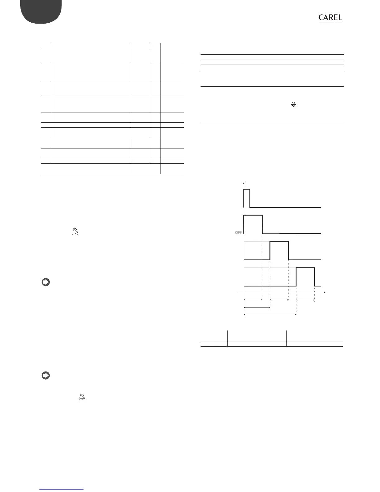
4 = IStart defrost from external contact
Application: this function is useful for performing defrosts in real time. To
perform the defrosts, connect a cyclical, mechanical or electronic timer
to the selected digital input: a series of units can be connected to the
same timer, setting diff erent values for parameter d5 (defrost delay from
multifunction input) to avoid simultaneous defrosts.
ON
OFF
ON
OFF
t
TIMER
OFF
dP(2)dP(1)
d5(2)
DEFROST
UNIT 1
UNIT 2
UNIT 3
DEFROST
ONON
OFF
ON
DEFROST
dP(3)
d5(1)=0
d5(3)
Fig. 5.b
Key
dP Maximum defrost duration d5 Defrost delay from
digital input
UNIT 1…3 Unit 1-3 t Time
5 = Door switch with compressor and evaporator fan o
Parameter d8 defi nes the high temperature alarm bypass time after
the defrost ends (or the door is opened). Parameter d8d is the alarm
bypass time after the door is opened. If d8d=0, the alarm delay after
door open coincides with the value of parameter d8. Setting “A4”=5
manages the cold room door switch. The behaviour of the door
switch depends on the status of the light when the door is opened:
1. light off ;
2. light on.