12
ENG
“SmartCella manual” +0300084EN - rel. 1.2 - 28.03.2017
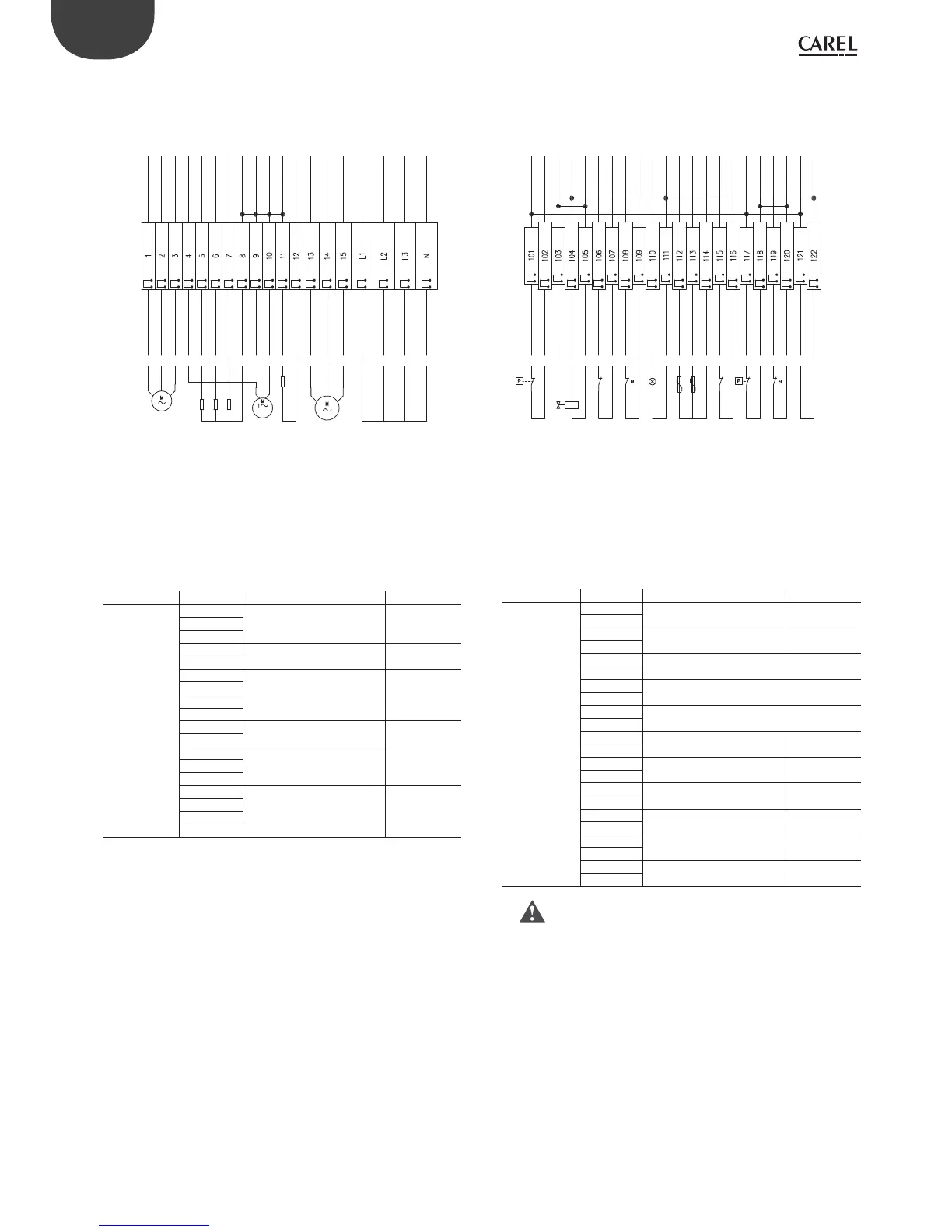
Code WP00B57B20, WP00B47B20
EVAPORATOR FAN
CONDENSER FAN
HEATERS
CARTER HEATER
COMPRESSOR
POWER INPUT
PRESSURE SWITCH LP
VALVE
THERMAL FAN
SAFETY THERMOSTAT
INTERNAL LIGHTS
AMBIENT PROBE
DEFROST PROBE
MICRO SWITCH
PRESSUR SWITCH HP/LP
COMPRESSOR KRIWAN
POWER SUPPLYKRIWAN
Terminal block XP1 Terminal block XA1
Fig. 2.i
Terminal block Number Description Type
XP1 1
Evaporator fan Output2
3
4
Condenser fan Output
10
5
Defrost heaters Output
6
7
8
11
Crankcase heater Output
12
13
Compressor Output14
15
L1
Power supply input Input
L2
L3
N
Tab. 2.e
Terminal block Number Description Type
XA1 101
LP pressure switch Input
102
104
Valve Output
105
106
Fan thermal protector Input
107
108
Safety thermostat Input
109
110
Inside lights Output
111
112
Room probe Input
114
113
Defrost probe Input
114
115
Door microswitch Input
116
117
HP/LP pressure switch (*)
Input
118
119
Compressor Kriwan (*)
Input
120
121
Kriwan power supply Output
122
Tab. 2.f
(*) Warning: if input 117-118 and/or 119-120 are not connected,
the control will show an “IA“ alarm.