30
ENG
“SmartCella manual” +0300084EN - rel. 1.2 - 28.03.2017
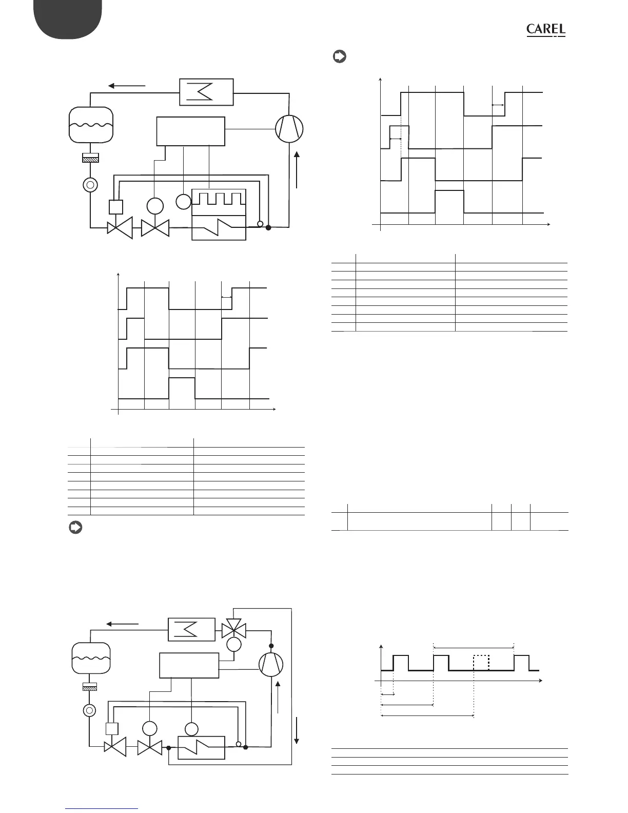
1. Heater defrost (d0 = 0, 2, 4): duty cycle
The duty cycle refers to the default values of parameters F2 and F3.
C
L
CMP
T
V2
E
S2
M
V_Pd
SmartCella
S
F
Fig. 6.l
ON
OFF
ON
OFF
t
CMP
V_Pd
ON
OFF
FAN
ON
OFF
RES
REFRIG PUMP
DOWN
DEF DRIP
(dd)
POST DRIP
(Fd)
REFRIG
c8
Fig. 6.m
Key
CMP Compressor Refrig Cooling
V_Pd Pump down valve Pump down Pump down stage
FAN Evaporator fan Def Defrost
RES Heater Drip Dripping
E Evaporator Post drip Post-dripping
C Condenser S2 Defrost probe
V2 Thermostatic expansion valve L Liquid receiver
F Filter-drier S Liquid gauge
t Time
Note:
• in pump down mode, the behaviour of the fan is determined by F2;
• in defrost, the behaviour of the fan is determined by F3.
2. Hot gas defrost (d0 = 1, 3): duty cycle
The duty cycle refers to the default values of parameters F2 and F3.
C
L
CMP
T
V2
E
S2
V_Pd
M
M
V_def
S
F
SmartCella
Fig. 6.n
Note: the defrost output (DEF) is used to control the hot gas valve V_def.
ON
OFF
ON
OFF
t
CMP
V_Pd
ON
OFF
FAN
ON
OFF
V_def
(HOT GAS)
REFRIG PUMP
DOWN
DEF DRIP POST
DRIP
REFRIG
c8
c8
Fig. 6.o
Key
CMP Compressor Refrig Cooling
V_Pd Pump down valve Pump down Pump down stage
FAN Evaporator fan Def Defrost
V_def Hot gas valve Drip Dripping
E Evaporator Post drip Post-dripping
C Condenser S2 Defrost probe
V2 Thermostatic expansion valve L Liquid receiver
F Filter-drier S Liquid gauge
t Time
The defrost starts:
• by setting the event and the start mode, with a maximum of 8 defrosts
each day (parameters td1 to td8). The real time clock (RTC) must be
available;
• from the supervisor, which sends the defrost call to each controller via
the serial line;
• from the keypad.
The defrost ends:
• when the defrost probe measures a temperature greater than the end
defrost temperature dt1;
• when no defrost probe is used, the defrost ends after a maximum time,
set by parameter dP1.
Maximum time between consecutive defrosts
Par. Description Def Min Max UOM
dI Maximum time between consecutive defrosts
0 = defrost not performed
8 0 250 hr/
min
Tab. 6.k
Parameter dI is a safety parameter used to perform cyclical defrosts
every “dI” hours, even without the Real Time Clock (RTC). It is also useful
if the RS485 serial network is disconnected. At the start of each defrost,
irrespective of the duration, an interval starts being counted. If this
interval exceeds dI without a defrost being performed, one is started
automatically. The count is always active even if the controller is OFF.
Example: if there is an RTC fault, the defrost programmed by td3 is not
performed, and after the safety time dI a new defrost starts.
ON
OFF
DEF
t
td1
td2
dI
td3
Fig. 6.p
Key
dI Maximum time between consecutive defrosts
td1…td3 Programmed defrosts
DEF Defrost
t Time