49
ENG
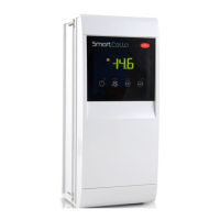
“SmartCella manual” +0300084EN - rel. 1.2 - 28.03.2017
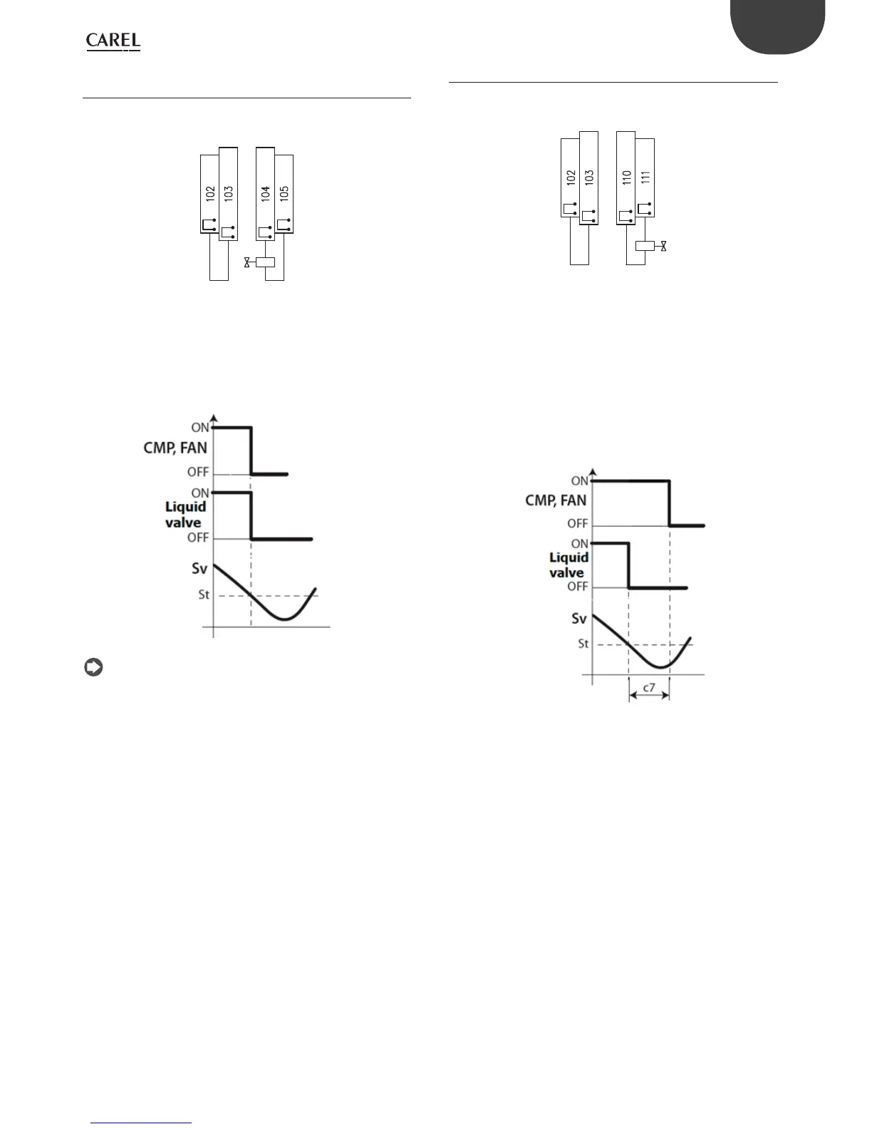
9.3.3 Connections for simultaneous compressor and
solenoid valve activation
If shutdown simultaneous compressor and solenoid valve activation
and deactivation are required, without using a pressure switch, the
connections are as shown in the following diagram
liquid valve
bridge
Fig. 9.i
In this confi guration, when there is no cooling request (Sv<St), the
deactivated valve (terminals 105-104) and the compressor (KM2) are off
simultaneously
Fig. 9.j
Note: do not enable pump down on Smartcella 3PH (check that
c7=0, H1≠5).
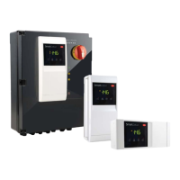
9.3.4 Connections for pump down by time
If solenoid valve needs to be activated and deactivated by time, without
using a pressure switch, the connections are as shown in the following
diagram
liquid valve
bridge
Fig. 9.k
On Smartcella 3PH confi gure:
• H1=5 (aux1 output, terminals 110-111, for pump down valve)
• C10=1 (pump down by time)
• C7>0 (pump down time)
In this confi guration, when there is no cooling request (Sv<St), the
solenoid valve relay (terminals 110-111, AUX1 output on Smartcella)
opens, while the compressor (KM2) operates for the time defi ned by
parameter C7
Fig. 9.l