43
▲
▲
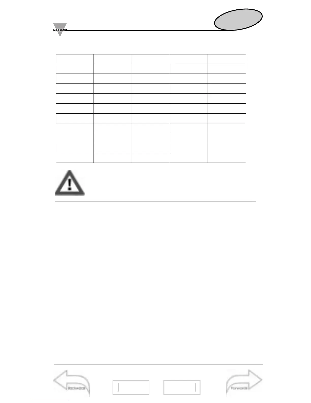
List of the available variables:
Useful information
What is ASY?
41
38
Position of the modules
47
The availability of the variables depends on the
type of electrical system being selected.
■
INSTALLATION
❑
Preliminary operations
Before switching the instrument on, make sure that the power
supply voltage corresponds to what is shown on the side label
of the relevant module. Example:
AP1020, Universal power supply
input range: 100V...240V DC/AC (50Hz -60Hz)
power consumption: 12W / 30VA 1 PHASE
serial number: S/N 002700/20345
❑
Before mounting the modules
Each module (input, output and power supply) must be
mounted in the proper slot: each module has been conceived
to be mounted in one slot only. To know in which slot every
module is to be mounted, refer to the figure on page 45.
V1LnA3LAVDHT
ll
2V3ADHT
2LV1LWAV ∑ DHT
I
2VDHT
II
3A
3LV2LW1LFP3VDHTDHT
I
3A
N-LV ∑ 3LW2LFPDHT
ll
3VdmdnA
2-1LVW∑ 3LFPDHT
l
3VdmdAV
3-2LV1LravFP ∑ 1ADHTgvaFP
1-3LV2LravzHDHT
ll
1AdmdW
V ∑ 3Lrav1VDHTDHT
l
1AYSA
1LArav ∑ DHT
ll
1V2ADHT
2LA1LAVDHT
l
1VDHT
ll
2A
3LA2LAV2VDHTDHT
l
2A
 Loading...