14
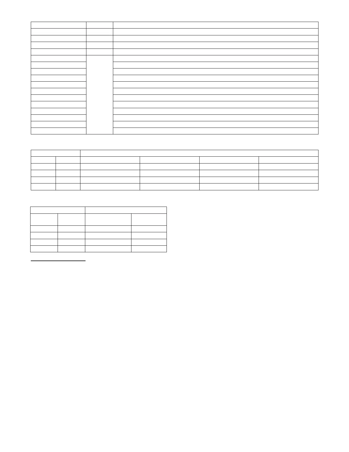
Table 8 – Demand List and Priority
DEMAND Priority Description
EMERGENCY 1 An emergency condition occurs which requires a unit shutdown
SAFETY FAULT 2 A safety diagnostic requires the unit to run in safety mode.
SERVICE TEST 3 User r equest test mode
SHUTDOWN 4 A minor or user condition requires the unit to shutdown
NO DEMAND
5
There is no comfort demand from the building
FAN ONL Y Only circulation or ventilation is requested form the building
DEHUM A dehumidification load is present in the building
LOW COOL A low cooling load is present in the building
HIGH COOL A high cooling load is present in the building
LOW COOL & DEHUM A low cooling and dehumidification load is present in the building
HIGH COOL & DEHUM A high cooling and dehumidification load is present in the building
UFC LOW COOL A low cooling load is present in the building due to the unoccupied free cooling algorithm
UFC HIGH COOL A high cooling load is present in the building due to the unoccupied free cooling algorithm
LOW HEAT A low heating load is present in the building
HIGH HEAT A high heating load is present in the building
SUPPL Y AIR TEMPERING Due to outside air, supply air is uncomfortably cool during ventilation
Table 9 – Thermostat Cooling System Demands
Thermostat Inputs THERMOSTAT TYPE
Y1 Y2 CONV 2C2H* CONV 3C2H DIGI 2C2H DIGI 3C2H
0 0 No Cool No Cool No Cool No Cool
0 1 Alert & Low Cool Alert & Low Cool High Co ol High Cool
1 0 Low Cool Low Cool Low Cool Low Cool
1 1 High Cool High C o ol High C ool High Cool
*SettheLOW COOL COMP as n eeded.
Table 10 – Thermostat Heating System Demands
Thermostat Input THERMOSTAT TYPE
W1 W2
CONV 2C2H
CONV 3C2H
DIGI 2C2H
DIGI 3C2H
0 0 No Heat No Heat
0 1 Alert & Low Heat High Heat
1 0 Low Heat Low Heat
1 1 High Hea t High Heat
Space Sensor Demand
When the unit control type is configured for space sensor (UNIT
CONTROL TYPE = SPACE SEN) the level 5 demand in T able 8
will be determined by the space sensor inputs and setpoints as
described below. The Effective Demand T emperature (DEMAND
CTRL TEMP) represents the temperature which the control is
using to control the space. This would come from the space sensor,
building network, linkage, or the return air sensor.
Setpoint Determination
Setpoints are used to control the unit. The Cool Setpoint in Effect
(EFF COOL SETPOINT) and the Heat Setpoint in Effect (EFF
HEAT SETPOINT) are the points in which the unit is controlling
to at a specific time. These points are read only points and change
according to occupancy, the offset slider status, and network writes.
The setpoint configurations are in the SETTINGSSPACE SET
POINTS submenu.
If the building is in occupied mode, the Occupied Cool Setpoint
(OCC COOL SETPOINT) and the Occupied Heat Setpoint (OCC
HEAT SETPOINT) are active. When the building is in
unoccupied mode, the Unoccupied Cool Setpoint (UNOCC COOL
SETPNT) and the Unoccupied Heat Setpoint (UNOCC HEAT
SETPNT) are active. The heating and cooling set points are also
separated by a Heat--Cool Set Point Gap (HEAT- COOL SP GAP)
that is user configurable from 2 to 10 degrees F. This parameter
will not allow the setpoints to be set too close together , it will
change the last setpoint adjusted if it is set within the GAP.
When the space sensor has a setpoint slider adjustment, the cool
and heat setpoints (occupied) can be offset by sliding the bar from
one side to the other. The SPT Offset Range (+/-- ) (SPT SLIDER
RANGE) sets the total positive or negative degrees that can be
added to the setpoints. With the slider in the middle, no offset is
applied. Moving the slider to the “COOL” side will subtract from
each setpoint, and sliding it to the “WARM” side will add to the
setpoints. The slider offset being applied at any given time is
displayed as Space Temperature Offset (SLIDER OFFSET VAL).
Temperature Demand
Space sensor staging control is an adaptive anticipation control that
weighs the actual space demand against the trend of that demand.
The control tries to anticipate the change in the space because of its
current stage status. This anticipation is based on the demand
trends. These trends will show the control how the space is reacting
to the current running conditions and help it decide when to
change the actual demand of the system. The following points are
in the RUN STATUSMODE submenu:
COOLING DEMAND — This is the difference between the Cool
Setpoint in Effect (EFF COOL SETPOINT) and the Effective
Demand Temperature (DEMAND CTRL TEMP) representing the
demand of the space for cooling.
COOL DEMAND TREND — This is the rate of change of the
cooling demand in degrees per minute, representing how the space
is changing its demand for cooling.
HEATING DEMAND — This is the dif ference between the Heat
Setpoint in Effect (EFF HEAT SETPOINT) and the Effective
Demand Temperature (DEMAND CTRL TEMP) representing the
demand of the space for cooling.
HEAT DEMAND TREND — This is the rate of change of the
heating demand in degrees per minute, representing how the space
is changing its demand for cooling.
In general the system demand will increase based on the demand
compared to the demand switch states in Fig. 9. The demand
cannot increase until Time guard 1 (DEMAND T IMEGUARD1)
expires. The LCON and LHON thresholds will also cause the

 Loading...


