41
Phase Protection
The phase loss protection option will monitor the three-phase electrical
system to provide phas e r eversal and phas e loss protection.
Phase Reversal Protection
If the control senses an incorrect phase relationship, the relay (K1)
will be de-energized (opening its contact). If the phase relationship
is correct, the relay will be energized. The control has a self-bypass
function after a pre-set time. If the control determines that the three
phases stay in a correct relationship for 10 consecutive minutes, the
relay will stay energized regardless of the phase sequence of three
inputs as long as 24-VAC control voltage is applied. This
self-bypass function will be reset if all three phases are restored in a
phase loss event.
Phase Loss Protection
If the re verse rot ation board se nses any one of the thr ee phas e input s
has no AC volt age, the relay wil l be de--energized (opening its
contact). This prot ecti on is always active as long as 24-VAC c ontrol
voltage is appl ied, and is not affected by the self by-pass function of
the phase sequence moni t oring function. Howeve r, i n the event of
phase loss, the relay will be re -ene rgiz ed only if all thr ee phases are
restored and t he three pha s es are in t he correct se quence .
A red LED is provided to indicate the function of the board. See
the table below.
LED STATUS FUNCTION
On Continuously Relay contact closed (normal operation).
Blinking
Relay contact open (phase loss or phase
reversal has occurred) — No power will be
supplied to the control system.
Off 24---VAC control power not present (off).
Thermistor Troubleshooting
The SystemVut controller uses thermistors to sense temperatures
used to control operation of the unit. Resistances at various
temperatures are listed in Table 20. Thermistor pin connection
points are shown in the Major System Components section. The
general locations of the thermistors are shown the Major System
Components section.
Air Temperatures
Air temperatures are measured with 10K thermistors. This includes
supply-air temperature (SAT), outdoor-air temperature (OAT),
space temperature sensors (T55, T56, T59), and return air
temperature (RAT).
The supply air temperature (SAT) and outdoor air temperature
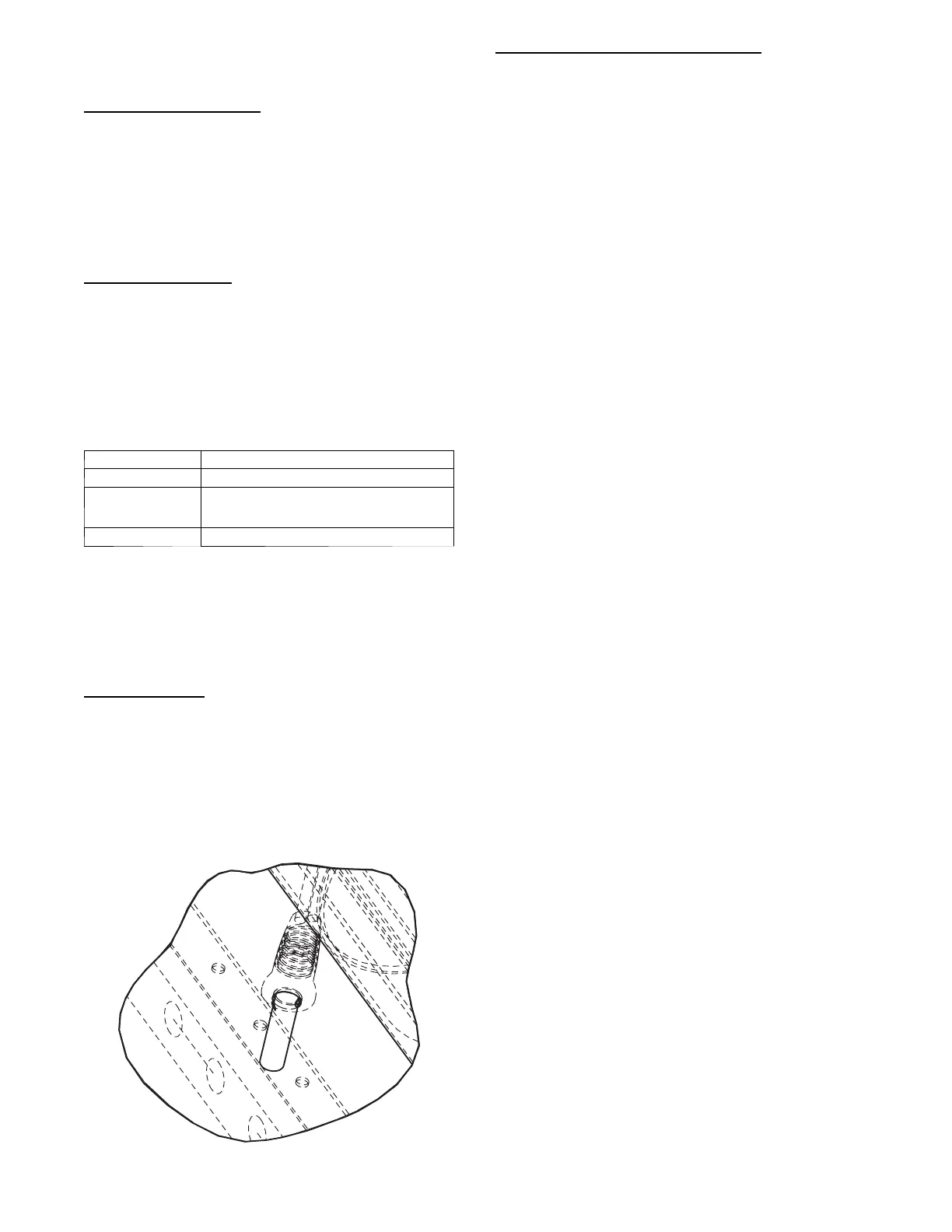
(OAT) thermistors use a snap-mount to attach through the unit
sheet metal panels. The snap-mount tabs must be flattened on the
tip end of the sensor to release for removal from the panel. (See
Fig. 20.) To reinstall, make sure the snap-mount tabs extend out.
C07015
Fig. 20 -- SAT and OAT Thermistor Mounting
Thermistor/Temperature Sensor Check
A digital volt-ohmmeter is required to perform this check.
Connect the digital volt-- ohmmeter across the appropriate
thermistor terminals at the J8 connector on the Main Base Board
(see Major System Components section).
Using the voltage reading obtained, read the sensor temperature
from Table 20 (on page 42).
To check thermistor accuracy, measure temperature at
probe location with an accurate thermocouple-type
temperature-measuring instrument. Insulate thermocouple to avoid
ambient temperatures from influencing reading. T e mperature
measured by thermocouple and temperature determined from
thermistor voltage reading should be close, within 5F if care was
taken in applying thermocouple and taking readings.
If a more accurate check is required, unit must be shut down and
thermistor removed and checked at a known temperature (freezing
point or boiling point of water) using either voltage drop measured
across thermistor at the J8 connector, or by determining the
resistance with unit shut down and thermistor disconnected from
J8. Compare the values determined with the value read by the
control in the Temperatures mode using the SystemVut display.
Sensor Trim
Corrective offsets can be applied to all the analog inputs. Trim can
be used as a form of calibration. The trim works by adding or
subtracting the specified amount on the specified analog input.
These corrections should only be use when a proper calibrated tool
is used to compare to the sensors reading. These corrections are
only applied to the local sensor values, a building systems (BAS)
communicating values will not account for these corrections. Use
the SERVIC E CALIBRATION menu on the SystemVu Di splay to
adjust these values.
Transducer Troubleshooting
The electronic control uses suction and discharge pressure
transducers to measure the pressure of the refrigerant circuits. The
pressure/voltage characteristics of these transducers are in shown in
Table 21 (on page 43) for suction transducers and Table 22 (on
pages 44 --45) for discharge transducers. The 5vdc power is applied
to legs A and B of the transducer and legs B to C represent the
signal voltage. To use the voltage drop table for troubleshooting,
read the voltage across A and B, then subtract the voltage reading
fro m B to C. The voltage drop can be looked u p in Table 21 and
Table 22 depending on the type of transducer. The accuracy of
these transducers can be verified by connecting an accurate
pressure gauge to the second refrigerant port in the suction and
discharge lines.

 Loading...


