13
CCH MAX T EMP
This configuration defines the temperature threshold for which the
crankcase heater is no longer required to heat the compressor shell.
STD BARO PRESSURE
This configuration is used to spe cify the job loc ation’s st andard
barometer pressure reading. This will feed the BAROMETRIC
PRESS when a network is not writing to it. This shoul d be used to
account for job si te elevation if enthalpy ca lculations are being use d.
LINK STAGEUP TIME
This configuration sets the cooling and heating stage up time
during linkage operation.
Configurable Switches and Analog sensors
The Syst emV ut controller has opti onal configurable inputs . Thes e
consist of five physi cal board swi t ch inputs (di screte input s) and three
physical boa rd ana l og input s. The r e are more functions al lowed for
configuration than the re ar e inputs. Each functi on wil l have a
configuration f or which input channel it i s assigned t o. Eac h swi t ch
function will also have a swi tch type configuration which defines tha t
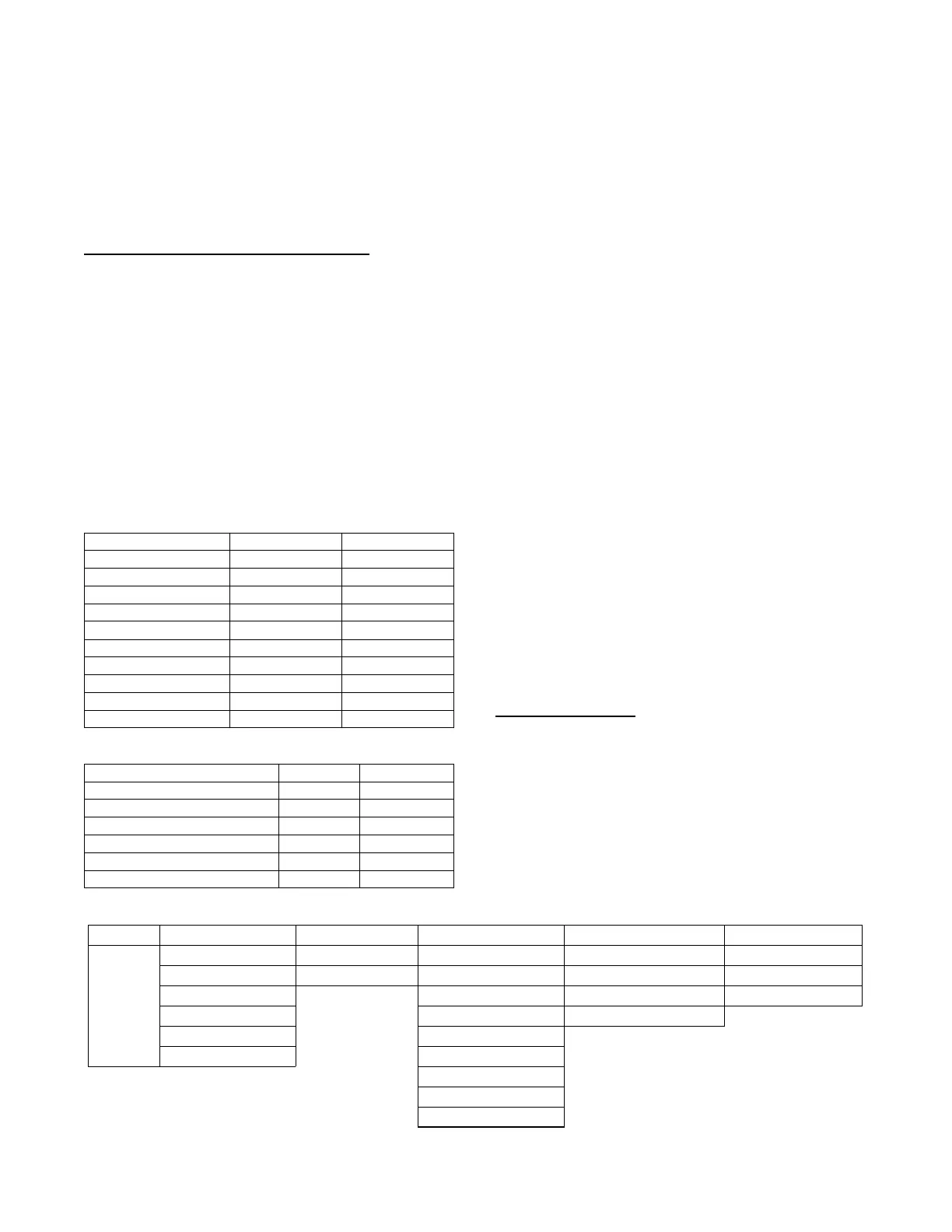
sw i tches normal state. Ta bl e 6 shows the configurable functions and
wha t the ir normal and ac tive states are. Tabl e 7 s hows the configurabl e
analog input func tions. The swi tch configurat ions c an be found in the
SETTINGSUNIT CONFIGURATIONSSWITCH INPUT
CONFIGS sub--me nu. The ana l og input conf igurations ca n be found
in the SETTINGUNI T CONFIGURATIONSSWITCH INPUT
CONFIGS sub--me nu. The configurable input assignm ent can be
viewed in the SER VICEHARDWAREASSIGNED
INPUTS/ OUTPUTS sub--menu.
Table 6 – Configurable Switch Input Functions
F unction Description Normal State Active State
Humidistat OFF ON
Condensate Overfl ow LOW HIGH
Phase Monitor NORMA L ALARM
Filter Status Switch CLEAN DIRTY
Remote Occupancy UNO CC OCCUP IED
Remote Shutdown RUN SHUTDOWN
Fan Status OFF ON
General Status Switch NORMA L ALARM
IAQ Override OFF ON
Enthalpy Switch Input LOW HIGH
Table 7 – Configurable Analog Input Functions
F unction Description Sensor Type Sensor Values
Space Relative Humidity Sensor 0 --- 2 0 mA %RH
Outside Air Relative Humidity Sensor 0 --- 2 0m A %RH
Return Air Relative Humidity Sensor 0 --- 2 0mA %RH
Indoor Air CO
2
Sensor 0 --- 2 0 mA PPM
Outside Air CO
2
Sensor 0 --- 2 0 mA PPM
Outdoor CFM Sensor 0 --- 2 0 mA CF M
General Operation
48/50FC and 48/50GC units can provide cooling,
dehumidification, heating, and ventilation. The operating mode
(MODE) shows the highest level of operation of the unit at any
given time. The operating sub --mode (SUB--MODE) shows the
detail operation occurring while under a specific mode. Fig. 8
shows the MODE and SUB-- MODE values.
Each unit will operate under one of three basic types of control,
thermostat, space temperature sensor, or return air temperature
sensor. There are many inputs, configurations, safety factors, and
conditions that ultimately control the unit. Refer to the specific
operation sections for detail on a specific unit operation. The
control will set the demand based on these types of control and
conditions, which then drives the operating mode.
When thermostat control is enabled (UNIT CONTROL TYPE),
the unit will operate based on discrete input commands (G, Y1,
Y2, W1, and W2) and there is a one minute time delay between
modes and when re--entering a mode. The G command calls for
ventilation, the Y1 and Y2 commands call for cooling, and the W1
and W2 commands call for heating. Thermostat Control Type
(THERMOSTAT TYPE) affects how cooling operates based on
Y1 and Y2 commands and if cooling/heating stage time guards are
applied.
When space temperature sensor control in enabled (UNIT
CONTROL TYPE), the unit will try to maintain the Space
Temperature (SPACE TEMPERATURE) between the effective
cool and heat setpoints (EFF COOL SETPOINT and EFF HEAT
SETPOINT). However, to minimize unnecessary cool to heat and
heat to cool changes, there is a 10 minute delay after the last stage
turns o ff before the control will switch modes. Linkage operation
overrides the mode changeover delay to 15 seconds. The cooling
and heating Mode Select Time guards (COOL MODE T.GUARD
and HEAT MODE T.GUARD) show the remaining time before
allowing the respective mode to be entered.
Demand Determination
Based on the unit control type (UNIT CONTROL TYPE),alarm
conditions, and user interaction, the control will determine an
overall demand of the unit. Table 8 shows the possible system
demands with their priority level and summary description.
Thermostat Demand
When the unit control type is configured for thermostat (UNIT
CONTROL TYPE = TSTAT) the level 5 demand in Table 8 will be
determined by thermostat inputs and the Thermostat Type
configuration (THERMOSTAT TYPE) as shown in the tables
below. Table 9 shows the cooling thermostat inputs and how they
map to the system demand. Table 10 shows the heating thermostat
inputs and how they map to the system demand.
SUB-
MODE
IDLE - NO DEMAND
SUPPLY FAN ON UNOCC. FREE COOL
MODE TIMEGUARD MECH. COOLING
UNIT DISABLED ECON/MECH COOLING
URGENT SHUTDOWN DEHUMIDIFICATION
SAFETY CONTROL DEHUM/MECH COOL
MODE OFF VENT COOL HEAT TEST
STARTING UP MODE TIMEGUARD ECON FREE COOLING HEATING MANUAL TEST
OUTSIDE AIR TEMPERING
HEATING PREVENTED
AUTO TEST
SHUTTING HEAT OFF
SHUTTING TEST OFF
DEHUM PREVENTED
COOLING PREVENTED
SHUTTING COOL OFF
a48---9374
Fig. 8 -- Modes and Sub--Modes

 Loading...


