25
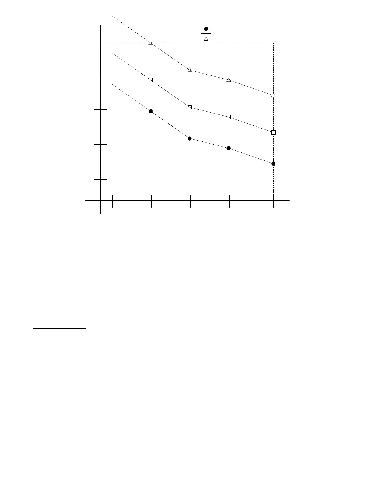
Indoor Fan Speed
Damper Position
Econo Max
Position
(DAMPMAX)
(MP_SPD2,
MP_POS2)
(MP_SPD3,
MP_POS3)
Maximum Speed
(SPEEDMAX)
(MP_SPD1,
MP_POS1)
10%
MINP_MAX
Minimum Position Curve
Key:
(PE1_SPD3,
PE1_POS3)
(PE1_SPD2,
PE1_POS2)
(PE1_SPD1,
PE1_POS1)
PE1PMAX
Power Exhaust 1Curve
(PE2_SPD3,
PE2_POS3)
2(PE2_SPD2,
PE2_POS2)
(PE2_SPD1,
PE2_POS1)
Power Exhaust 2 Curve
PE2PMAX
C14327
Fig. 17 -- Power Exhaust Opera tion Curves
Indoor Air Quality (IAQ)
Indoor air quality is typically measured using a CO
2
sensor whose
measurements are displayed in parts per million (ppm). Outdoor air
quality may be measured with a CO
2
sensor for indoor--outdoor
differential demand ventilation control. The factory--installed
indoor air quality CO
2
sensor is mounted in the return section. A
field--installed indoor air quality CO
2
sensor may be mounted in
the return or in the occupied space. The indoor air quality modes of
operation can be affected by the IAQ Analog Input Config
(ANALOG IAQ CTRL) and other related and limit configurations
as described below.
IAQ (Analog Input)
When IAQ assigned channel (IAQ SENSOR CHAN) is set for an
analog input that input channel will be mapped to the Indoor Air
Quality (IAQ LEVEL). The control is configured for indoor air
quality sensors which provide 4 to 20 mA signal for 0 to 2000 ppm
CO
2
. If the sensor being used has a different range, the ppm
display range must be reconfigured by entering new values for the
IAQ Sensor Value at 4mA (IAQ PPM @ 4MA) and IAQ Sensor
Value at 20mA (IAQ PPM @ 20MA).
ANALOG IAQ CTRL =0(NoIAQ)
This signifies that there is no IAQ sensor installed. The economizer
damper will operate based on the minimum position curve.
ANALOG IAQ CTRL = 1 (DCV)
During Demand Controlled Ventilation (DCV), the damper
modulates on or between two ventilation curves depending upon
the difference between the Indoor Air Quality (IAQ LEVEL) and
the Outdoor Air Quality (OAQ LEVEL). The lower of these two
curves is referred to as the IAQ Minimum Position Curve, and the
higher curve is the Minimum Position curve discussed in the
Minimum Ventilation section under Economizer Operation. Refer
to that section on how the minimum Position curve is created. See
Example Curves in Fig 16.
The IAQ Minimum Position curve is created by applying the
difference of the IAQ position at maximum fan speed (IAQ POS @
MAX SPD ) and the Economizer minimum at maximum fan speed
(MIN POS @ MAX FAN) in relationship to the minimum position
curve. The IAQ position at maximum fan speed (IAQ POS @
MAX SPD ) should be set to an economizer position that brings in
enough fresh air to remove contaminates and CO
2
generated by
sources other than people. The Economizer minimum at maximum
fan speed (MIN POS @ MAX FAN) should be set to an
economizer position that brings in fresh air to remove contaminates
and CO
2
generated by all sources including people when the
indoor fan is operating at the IDF Maximum Fan Speed
(MAXIMUM IDF SPEED). The Economizer minimum at
maximum fan speed (MIN POS @ MAX FAN) value is the design
value for maximum occupancy.
The economizer Min Position in Effect (EFFECTIVE MIN POS)
will follow the IAQ Minimum Position curve while the Indoor Air
Quality level (IAQ LEVEL) is less than the Outdoor Air Quality
Level (OAQ LEVEL). The control will begin to open the damper
more than the IAQ Minimum Position curve when the IAQ level
begins to exceed the OAQ level by a configurable amount. This
amount is referred to as AQ Differential Low (LOW AIR.Q
DIFF). When the differential between IAQ and OAQ reaches AQ
Differential High (HIGH AIR.Q DIFF), the economizer Min
Position in Ef fect (EFFECTIVE MIN POS) will follow the
Minimum Position Curve. When the IAQ/OAQ differential is
between AQ Differential Low (LOW AIR.Q DIFF) and AQ
Differential High (HIGH AIR.Q DIFF), the control will modulate
the damper between the IAQ Minimum Position Curve and the
Minimum Position Curve in a linear manner as shown as the
shaded area in Fig. 16. As a simple example Fig. 18 shows the Min

 Loading...


